


USSC 13
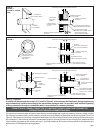
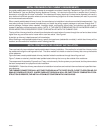
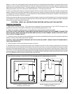
FIGURE 9 -
PLAN VIEWS SHOWING FLOOR PROTECTOR'S MINIMUM SIZE (DIMENSIONS IN INCHES)
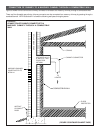
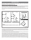
Masonry, or other non-combustible products, attached directly to a combustible surface without an air space offer very little
protection and cannot be considered a clearance reducer unless specified materials have been tested and listed for direct
attachment to a combustible surface. The same applies to thin veneer brick and stone coverings. These materials provide
adequate protection only when mounted on sheet metal with a 1 inch spacing to the wall.
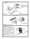
A variety or prefabricated clearance reduction systems which have been tested and listed are available through heater
dealers. Always look for a safety listing label on the product when selecting a clearance reduction system and make sure
it is designed for solid fuel appliances. The manufactures of these systems provide specific installation instructions that
must be followed exactly for a safe installation.
Should you choose to make your own clearance reduction system, contact your local fire department, fire marshal or building
code inspector for specific requirements regarding home constructed clearance reduction systems and safe installation
clearances to protect combustible materials.
CAUTION: READ ALL INSTRUCTIONS BEFORE INSTALLING THE HEATER.
TO INSTALL THE HEATER:
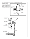
1. Make ready a suitable chimney. The chimney must complywith the requirements for Type 103-HT chimneys in the
standard for chimneys, Factory Built, Residential Type and Building Appliances, UL 103.
2. Gather the necessary materials, tools, and supplies which will be needed to install the heater.
CAUTION: DO NOT USE MORE THAN ONE 90 DEGREE BEND (ELBOW) IN THE CHIMNEY CONNECTOR
INSTALLATION. MORE THAN ONE 90 DEGREE BEND (ELBOW) IN THE CHIMNEY CONNECTOR COULD NEGA-
TIVELY AFFECT CHIMNEY DRAFT.
3. I f the floor on which the heater is to be installed is wood or any other combustible material, place a floor protector (described
earlier) on the floor where the heater will be installed.
CAUTION: THE FLOOR PROTECTOR MUST NOT BE PLACED ON CARPET. REMOVE CARPET FROM BENEATH
THE FLOOR PROTECTOR.
4. Place the heater on the floor protector as shown in Figure 9.
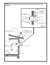
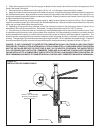
5. Assemble the chimney connector stove pipe from the heater's flue collar to the chimney to determine if the chimney
connector pipe will correctly extend from the heater's flue collar to the chimney. Any horizontal section of chimney connector
stove pipe must slope upward at least 1/4-inch rise to the horizontal foot to help maintain a sufficient draft. Always install
the chimney connector pipe with the crimped end toward the heater to prevent creosote or soot from leaking out of the chimney
connector pipe joints. MAKE SURE CLEARANCES TO COMBUSTIBLES ARE MAITAINED AS SPECIFIED BY FIGURE
8 IF A CLEARANCE REDUCTION SYSTEM IS NOT INSTALLED.
2
2
8888
16
8
16
8
FLOOR PROTECTOR
FLOOR PROTECTOR
WHEN CHIMNEY CONNECTOR EXITS
THROUGH THE CEILING
WHEN CHIMNEY CONNECTOR EXITS
THROUGH THE WALL