Oil Burner and Controls Start-Up and Adjustment
INDOOR CHIMNEY VENTED BOILERS
Instruction manual enclosed in burner carton must be
followed in regard to start-up and adjustment
1. Standard Beckett AFG or CF375 Oil Burner
A Beckett model AFG oil burner is normally supplied with boilers
to be fired at 2.00 gph or less. It is equipped with an F3 flame
retention head, the size most commonly used. It is possible the
head must be changed to match the nozzle firing rate
required, and it is recommended the installer carry a complete
assortment of Beckett flame retention heads. When head ratings
overlap, a smaller head with air shutter fairly well open will
generally provide better combustion than a larger head with air
shutter near closed. See head size selection chart on page 16.
For Beckett burners at firing rates above 2.00 gph, a Beckett
model CF375 burner is required, and is supplied if specified by
purchaser.
2. Optional Riello 40 Series Oil Burner
Riello 40 series oil burner is optional. Model F5 is used for firing
rates from 0.90 to 1.50 gph, and Model F10 is used for firing
rates from 1.60 to 3.00 gph. Model F5 or F10 is supplied if
specified by purchaser. For firing rates below 0.90 gph, a Model
F3 is required, and must be purchased from a Riello distributor.
SUGGESTED NOZZLES, HEADS, AND PRELIMINARY
SETTINGS FOR VARIOUS FIRING RATES AND BURNERS
ARE SHOWN ON PAGES 40 AND 41.
3. On knockdown boilers, the burner is not supplied with a
nozzle. The correct nozzle is the smallest which will do the job
properly. Long continuous runs with minimum starts and stops
conserve the most energy. The nozzle which provides the highest
C02 with the least smoke for a particular application is always
recommended. Beckett Oil burners are supplied with pump
pressure set at 140 psi. Nozzle output will be approximately
18% greater than that at 100 psi. Pump pressure on Riello
burners should be adjusted according to settings on page 41.
4. WARNING: Too low a firing rate can cause excessive
condensation within the boiler and chimney resulting in
severe rust and corrosion. A piping by-pass is recommended to
minimize this problem. See page 14.
15
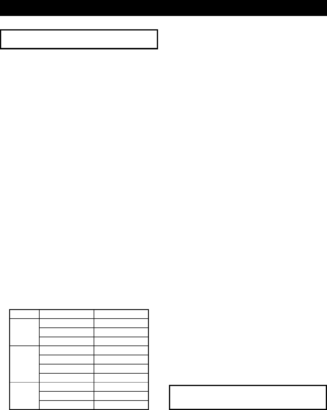
5. If Beckett AFG burner is to be fired at less than 1.00 gph, it is
possible that a low firing rate baffle will be required. For firing
rates not specified on page 40, see chart below on which an
x indicates that a baffle is necessary. See also instruction
sheet with baffle in burner carton.
6. Using three acorn nuts, studs and washers from hardware
package, fasten burner to mounting plate.
7. Mount L8151 control on boiler jacket above and to the right
of burner using sheet metal screws in holes located in jacket.
Wiring harness is provided. When well is used at the rear of
a larger boiler, it might be necessary to relocate the control
with longer wiring not provided.
8. If the boiler is equipped with a tankless coil, insert well for
the L8151 remote bulb in coil plate. Run capillary tube through
sight glass opening in jacket.
9. If a tankless coil is not used, install 3/4" well and bulb with a
bushing either in the 1 1/2" supply opening opposite the one
used to feed radiation, or in a reducing tee in the 1 1/2" supply
opening that actually feeds radiation.
10. Wiring diagram is found on page 16. To avoid excessive
condensation, do not use a two-stage thermostat or other
fuel saving devices or techniques without first contacting the
factory.
11. BEFORE MAKING CONTROL ADJUSTMENTS, verify that
all fuel, water and electrical connections have been made in
accordance with the regulations of the National Fire
Prevention Association, the National Electrical Code and/or
local regulations.
12. See page 14 for control settings.
13. Start-Up and Adjustment: Start and adjust burner according
to manufacturers instructions contained in burner carton or
included with packaged boiler, and pay special attention to
the following:
a. As the name suggests, this boiler is designed to produce
the ultimate in useable heat from a gallon of fuel oil. To
adjust the air-fuel mixture by eye is to waste fuel and
create soot.
b. Repeat - Do not adjust air by eye. Any time air
adjustment or oil rate is changed, combustion must be
checked with instruments.
c. With chamber fully warmed up, find the highest C02 level
at which zero smoke can be maintained. Then add extra
air until C02 falls off 1%. Final setting should be at least
11% C02. If unable to obtain that reading, check for
internal oil leaks, incorrect flame retention head or a faulty
or incorrect nozzle. (See charts on page 16.) Draft will
vary as air is adjusted. It should be left at as near zero
as possible at breeching.
Complete installation must be made in accordance with the
requirements of local authorities and the National Fire
Protection Association
HEAD FIRING RATE, GPH LOW FIRE BAFFLE
.50 X
.65 X
.75 —
.75 X
.85 X
.90 —
1.00 —
.85 X
.90 X
1.00 —
F0
F3
F6


