


Installation & Service Manual NSSD
March, 2002 Page 7
Defrost Information
See “General-UL/NSF I&S Manual” for
operational descriptions for each type of
defrost control.
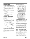
Defrost Control Chart
Defrost
Defrost Defrosts Duration Term.
T
ype Per Day (Min) Temp.
Off Time 6 28 ----
Electric 6 36 50°F
Gas 6 12-15 55°F
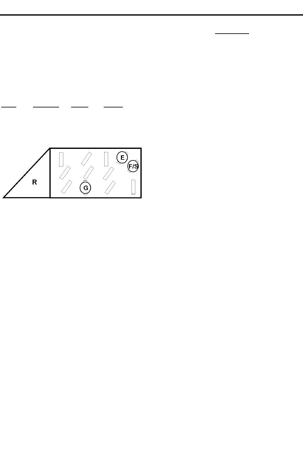
E = Electric Defrost Termination
G = Gas Defrost (Fan Delay)
F/S = Electric Defrost Failsafe (Opt.)
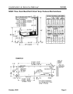
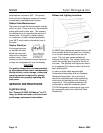
NOTE
The termination klixon for gas defrost is
located at the bypass check valve at the
left end of the evaporator coil.
Most klixons are located on the right end of
the evaporator coil. The diagram shows the
location for each defrost type that uses a
klixon.
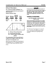
CAUTION
If electronic sensors are used in place of
the klixons, the sensors must be located in
the same location as the klixons for that
defrost type. Any other locations will
effect the refrigeration efficiency of the
case.
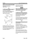
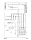
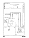
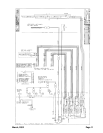
WIRING DIAGRAMS
ELECTRICIAN NOTE - OVERCURRENT
PROTECTION
120V circuits should be protected by 15 or 20 Amp
devices per the requirements noted on the cabinet
nameplate or the National Electrical Code, Canadian
Electrical Code - Part 1, Section 28. 208V defrost
circuits employ No. 12 AWG field wire leads for field
connections. On remote cases intended for end to
end line-ups, bonding for ground may rely upon the
pull-up bolts.
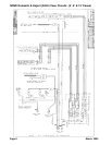
The following wiring diagrams on pages 8
thru 11 will cover the NSSD case circuits
including all defrost and lighting wiring
circuits.