


NSSD Tyler Refrigeration
Page 6 March, 2002
INSTALLATION PROCEDURES
Carpentry Procedures
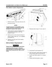
Case Line-Up
NOTE
The NSSD cases are shipped on casters that
are replaced with adjustable legs during
case line-up and installation.
See the “General-UL/NSF I&S Manual” for
the proper case line-up procedures.
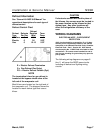
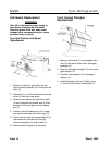
Case Pull-Up Locations
All NSSD models have four pull-ups at each
end of the case. Pull-ups A, B, C and D are
located as shown and should be installed and
tightend starting with A and finishing with D.
See “General-UL/NSF I&S Manual” for line-
up assembly instructions.
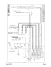
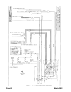
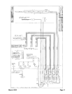
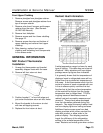
Electrical Procedures
Electrical Considerations
CA
UTION
Make sure all electrical connections at com-
ponents and terminal blocks are tight. This
prevents burning of electrical terminals
and/or premature component failure.
NOTE
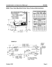
The NSSD has two raceway locations that
can house the electrical wiring, components
and terminal blocks. All components and
wiring can be located in either the lower
front or the lower rear of the case.
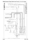
Case Fan Circuit
This circuit is to be supplied by an uninterrupt-
ed, protected 120V circuit. The case fan circuit
is not cycled, except when equipped for gas
defrost. On gas defrost cases the fan circuit is
controlled by a 50/40 klixon.
NOTE
With gas defrost, the fans will not start until
the coil temperature reaches 40°F at the fan
delay thermostat.
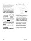
Fluorescent Lamp Circuit
Case lighting is supplied by T-8 electronic
ballast lights. It is controlled by a light switch
in each case. The standard lighting is 1-row of
T-8 canopy lights. NSSD models also offer up
to 3 rows of optional T-8 shelf lights.
Anti-Sweat Heater Circuit
NSSD cases have three anti-sweat heaters.
One in the top light assembly, one in the front
glass trim rail and one in the front glass retain-
er. All anti-sweat heaters are wired directly to
the main power supply so they can operate at
all times.