


R
Mechanical
Specifications
WSHP-PRC003-EN
187
Three LEDs (light emitting diodes) shall
be included for diagnostics of the
equipment.
The ZN510 shall be capable of a stand-
alone application, or as applied to a full
building automation installation.
Tracer ZN524 Controller (option)
The ZN524 controller shall utilize facto-
ry furnished and mounted DDC controls
for operation of up to 120 units on a
Comm 5 (LonMark) link. The Tracer
ZN524 control package shall include a
75 VA (minimum) transformer. The con-
troller shall provide random start delay,
heating/cooling status, occupied/unoc-
cupied mode, fan status and filter main-
tenance options. Optional wiring from
the factory for condensate overflow
shall be available. Three LEDs (light
emitting diodes) shall be included for
diagnostics of the equipment.
The ZN524 shall be capable of a stand-
alone application, or as applied to a full
building automation installation.
With this controller, the unit shall be
capable of a hot gas reheat (for dehu-
midification), boilerless control for elec-
tric heat, waterside economizing, and
support of variable speed pump control
applications.
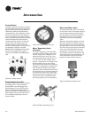
Orifice Ring
Removal of the motor and fan wheel
for the 1/2 through 5-ton units shall be
made with the assistance of a factory
provided orifice ring device. This device
shall attach the wheel and motor to the
fan housing in one assembly providing
single side service access.
Water Regulating Valve
Assembly
(option)
The water regulating valve assembly
shall consist of a direct acting valve and
a reverse acting valve. The direct acting
valve shall open in response to an
increase in discharge pressure during
the cooling cycle. The reverse acting
valve shall open in response to a
decrease in suction pressure during the
heating cycle. Water regulating valves
shall be used where low flow, or low or
high fluid temperature conditions exist.
This accessory shall be used with open-
loop systems.
Economizing Coil (GEH option)
The waterside economizing package
shall be an external unit accessory pre-
piped and pre-wired ready for turn-key
installation to the unit. The economizing
coil shall be designed to perform with
the WSHP at unit measured flow rate of
80.6 F DB/66.2 F WB with 45 F EWT.
All hydronic coils shall be of 5/8" cop-
per and aluminum plate fin combina-
tion. All coils shall be proof and leak
tested from the manufacturer. The proof
test shall be performed at 1.5 times the
maximum operating pressure and the
leak test at the maximum operating
pressure.
A dual sloped non corrosive drain pan
shall be easily accessible and cleanable
for the hydronic economizing coil.
An electronic two-position, 3-way valve
shall meter water flow to the economiz-
ing coil during the economizing mode.
It shall be factory set to energize the
economizing mode at 55 F, while simul-
taneously halting mechanical operation
of the compressor.
Hanging brackets with rubber isolation
shall be provided for the horizontal ver-
sion of the economizing coil option. The
bracket design shall be the same
throughout the equipment.
Electric Heat (option)
Boilerless control electric heat shall be
factory wired and tested. It shall be
composed of a nichrome open wire coil
designed for 2-kW per unit ton. The
design consist of a single stage of elec-
tric heat used as a primary heating
source when compressor lockout has
occurred due to the entering water tem-
perature falling below 55 F with an
adjustable range between 25 F to 60 F.
All power connections to the electric
heat shall be made in the equipment’s
control box.
Hot Gas Reheat (option)
Dehumidification shall be provided
through a hot gas reheat option. The
coil shall consist of 3/8"/1/2" copper
tubes mechanically expanded into
evenly spaced aluminum fins. All coils
shall be proof and leak tested. The
proof test must be performed at 1.5
time the maximum operating pressure
and the leak test performed at the max-
imum operating pressure.
Ball Valves (option)
Ball valves shall be field installed
between the unit and the supply and
return lines of the loop to stop water
flow to the unit in a maintenance or
service situation.
Motorized Water Valve (option)
When extreme fluid temperature condi-
tions do not exist with an open loop
system, a motorized water valve shall
be applied to each water-source heat
pump. The motorized valve shall stop
flow to the unit, causing pressures to
rise. This rise in pressure will halt pump
operation to provide greater energy
savings of the entire system.
Pump Module (option)
The pump module shall be a complete
self contained pumping package for an
earth-coupled heat pump system.
The module shall consist of a single,
1/6-HP bronze pump, and a brass 3-way
shut-off valve. These kits shall contain
the necessary components for the
installation, operation, and mainte-
nance of the water circuit of a closed-
loop distributed pumping application.