


R
Accessories
WSHP-PRC003-EN
183
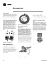
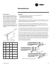
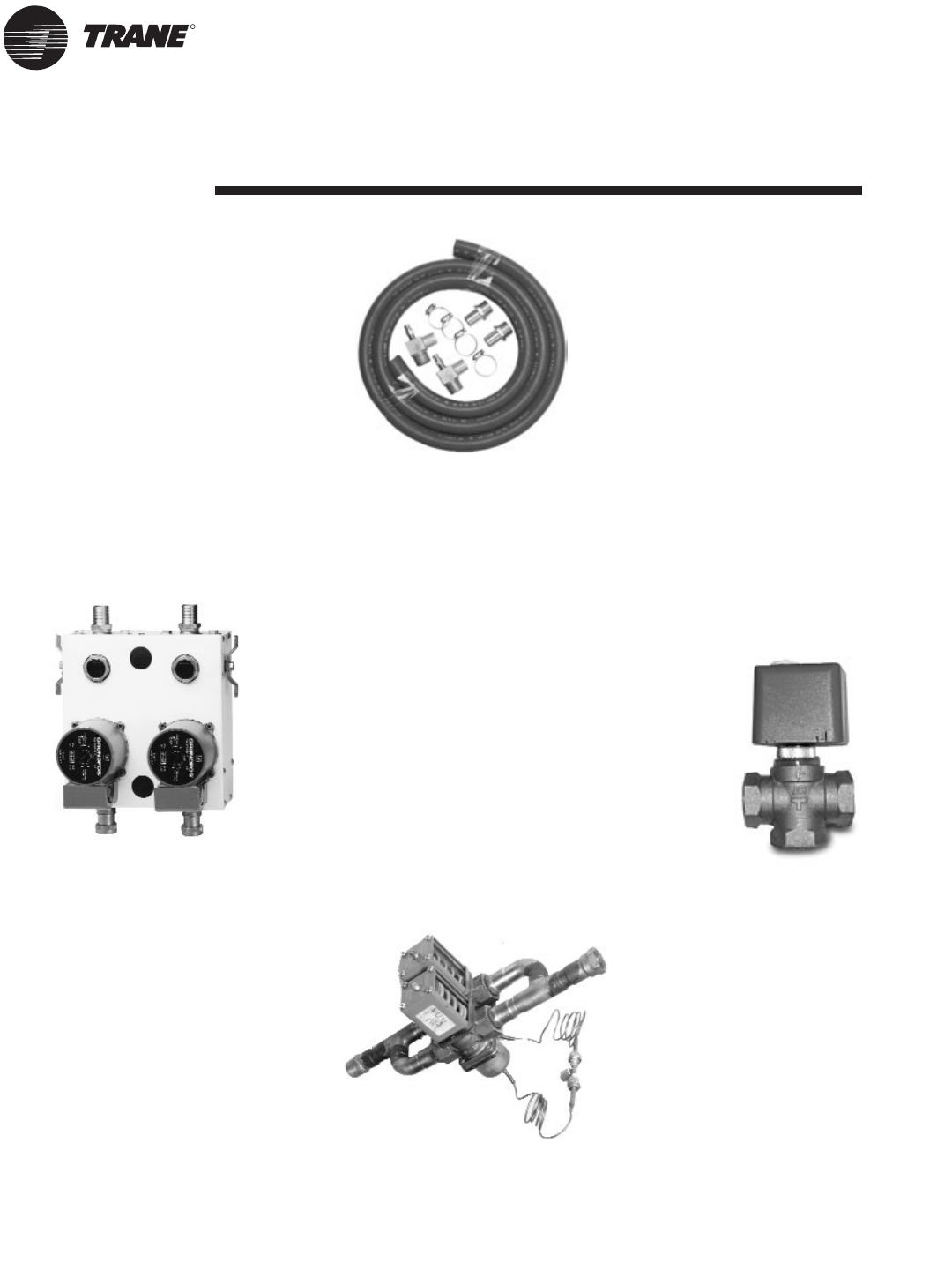
Pump Module
The pump module and hose kit make a
complete self-contained pumping pack-
age for distributed pumping systems.
These kits contain all the necessary
components for the installation, opera-
tion and maintenance of the water cir-
cuit of a closed loop geothermal appli-
cation. Standard pump module features
include insulated Grundfos pumps,
insulated cabinet, bronze or cast iron
pump, and 3-way brass valves. The
module is factory piped, wired and
mounted. See Figure 40 for pump mod-
ule assembly. Literature number
WSHPC-IN-5 (72-9006-03) will provide
electrical and dimensional require-
ments for the PMCA and PMBA prod-
ucts.
Figure 37: Pump module
Pump Module Hose Kit
The pump module hose kit consists of
two brass, 3/4 or 1-inch male pipe
thread (MPT) -by-barb fittings; two
brass 90 degree 1-inch, MPT-by-barb
elbows with pressure/temperature
ports; and 10 feet of rubber hose with 4
hose clamps. The pump module hose
kit is available separately from the
pump module.
Figure 38: Pump module hose kit
Water Regulating Valve
Assembly
The water regulating valve assembly
consists of a direct acting valve and a
reverse acting valve installed on the
water-out side of the unit. The valve
connection sizes shall range from 1/2"
to 1 1/2" FPT. The direct acting valve
opens in response to an increase in dis-
charge pressure during the cooling
cycle. The reverse acting valve opens in
response to a decrease in suction pres-
sure during the heating cycle. Water
regulating valves should be used where
low flow and low or high fluid tempera-
ture conditions could occur. See page
29 of this manual for application infor-
mation.This option is beneficial with
open loop systems, but not necessary.
Figure 39: Water regulating valve
Motorized Water Valve
The motorized water valve is installed
on the return line of the water loop sys-
tem between the loop and the loop’s
pump module. This isolation device is
less expensive and a very effective
alternative to the water regulating
valve.
When the compressor begins running,
the valve will open, allowing water to
flow through the unit. As the compres-
sor shuts down, the valve slowly closes
off. The main purpose of the motorized
valve is to shut-off the flow of water
through the unit when the unit is off,
thus reducing water consumption. The
motorized valve is fast opening to pre-
vent compressor trip-out, and slow
closing to prevent water hammer.
Figure 40: Motorized water valve