


Mechanical
Specifications
WSHP-PRC003-EN
R
186
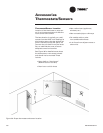
When the unit is installed and trapped
per the manufacturers installation man-
ual, and local city specifications, the
drain pan shall be designed to leave
puddles no more than 2-inch in diame-
ter, no more than 1/8-inch deep, no
longer than 3-minutes following Step 3
of the following test:
1. Temporarily plug the drain pan.
2.Fill the drain pan with 1/2-inch of
water or the maximum allowed by
the drain pan depth, whichever is
smaller.
3.Remove the temporary plug.
Water-to-Refrigerant Heat
Exchanger
The water-to-refrigerant heat exchanger
shall be of a high quality co-axial coil
for maximum heat transfer. The copper
or optional cupro-nickel coil shall be
deeply fluted to enhance heat transfer
and minimize fouling and scaling. The
coil shall have a working pressure of
400 psig on both the refrigerant and
water sides. The factory shall provide
rubber isolation to the heat exchanging
device to enhance sound attenuation.
Indoor Fan
The blower shall be a forward-curved
style wheel with four speed combina-
tions, or nine blower motor/sheave
combinations available.
All direct drive motors shall have
sealed bearings that do not require
field lubrication.
Options of the blower motor/fan pack-
ages shall be selected and wired from
the factory to match performance crite-
ria suggested in the performance sec-
tion. The motor shall contain a quick
disconnect plug for service, convertibili-
ty and safety precautions.
The fan(s) shall be placed in a draw-
through configuration. They shall be
constructed of corrosion resistant gal-
vanized material.
Electrical
The unit control box shall contain all
necessary devices to allow heating and
cooling operation to occur from a
remote wall thermostat. These devices
shall be as follows:
• 24 VAC energy limiting class II
50 VA (minimum) transformer
• 24 VAC blower motor relay
24 VAC compressor contactor for
compressor control
• Field thermostat connections shall
be provided for ease of hook-up to
a terminal strip located in the unit’s
control box
• Lockout relay which controls
cycling of the compressor shall be
provided to protect the compressor
during adverse operating condi-
tions. The device may be reset by
interrupting power to the 24 VAC
control circuit. Reset may be done
either at a remote thermostat or
through a momentary main power
interruption
• A high pressure switch shall protect
the compressor against operation
at refrigerant system pressures
exceeding 395 psig.
• The low-water temperature switch
or sensor shall prevent the
compressor operation with leaving
water temperatures below
20 F/-6 C.
• Factory installed wire harness shall
be available for the Basic, Deluxe,
ZN510 and ZN524 control packages.
Nameplate information shall be provid-
ed for the application of either time-
delay fuses or HACR circuit breakers for
branch circuit protection from the pri-
mary source of power.
Basic Controls (option)
The basic control package shall contain
a low and high pressure switch along
with a compressor lockout relay for
control assistance. High voltage power
connections shall be made at the equip-
ments contactor. An optional conden-
sate overflow detection device shall be
made available with this control pack-
age. Each device shall be factory
mounted, wired, and tested in the
equipment.
Deluxe Controls (option)
The deluxe control package shall pro-
vide a 75 VA transformer with circuit
breaker. The controller shall include a
lockout relay, anti-short cycle compres-
sor protection, random start delay,
brown-out protection, low pressure
time delay, compressor delay on start
and an open relay for night setback or
pump request.
Optional wiring from the factory for
night setback, condensate overflow, hot
gas reheat, electric heat, and compres-
sor enable shall also be provided. Three
LEDs (light emitting diodes) shall also
be included for diagnostics of the
equipment.
Tracer ZN510 or ZN524
Controller (option)
This system shall utilize factory fur-
nished and mounted DDC controls for
operation of up to 120 units on a Comm
5 (LonMark) link. The Tracer ZN510 con-
trol package shall include a 75 VA trans-
former. The controller shall provide ran-
dom start delay, heating/cooling status,
occupied/unoccupied mode, fan status
and filter maintenance options.
Optional wiring from the factory for
condensate overflow shall be available.