


Accessories
WSHP-PRC003-EN
R
184
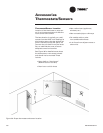
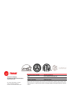
Ducted Panel
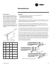
The return-air arrangement may be
easily converted from a free return-air
system, to a ducted return-air system
with the addition of a return-air side
panel. By replacing the filter racks with
the return-air panel, a complete seal
from the duct to the unit is possible.
The 1-1/2"(38mm) duct flange facili-
tates ease of field connection to the
mechanical system. This accessory is
typically used when the return-air filter
is placed in a built-in ceiling grille, or
placed within a field provided filter rack
assembly.
Figure 41: Return-air duct panel
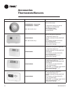
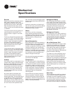
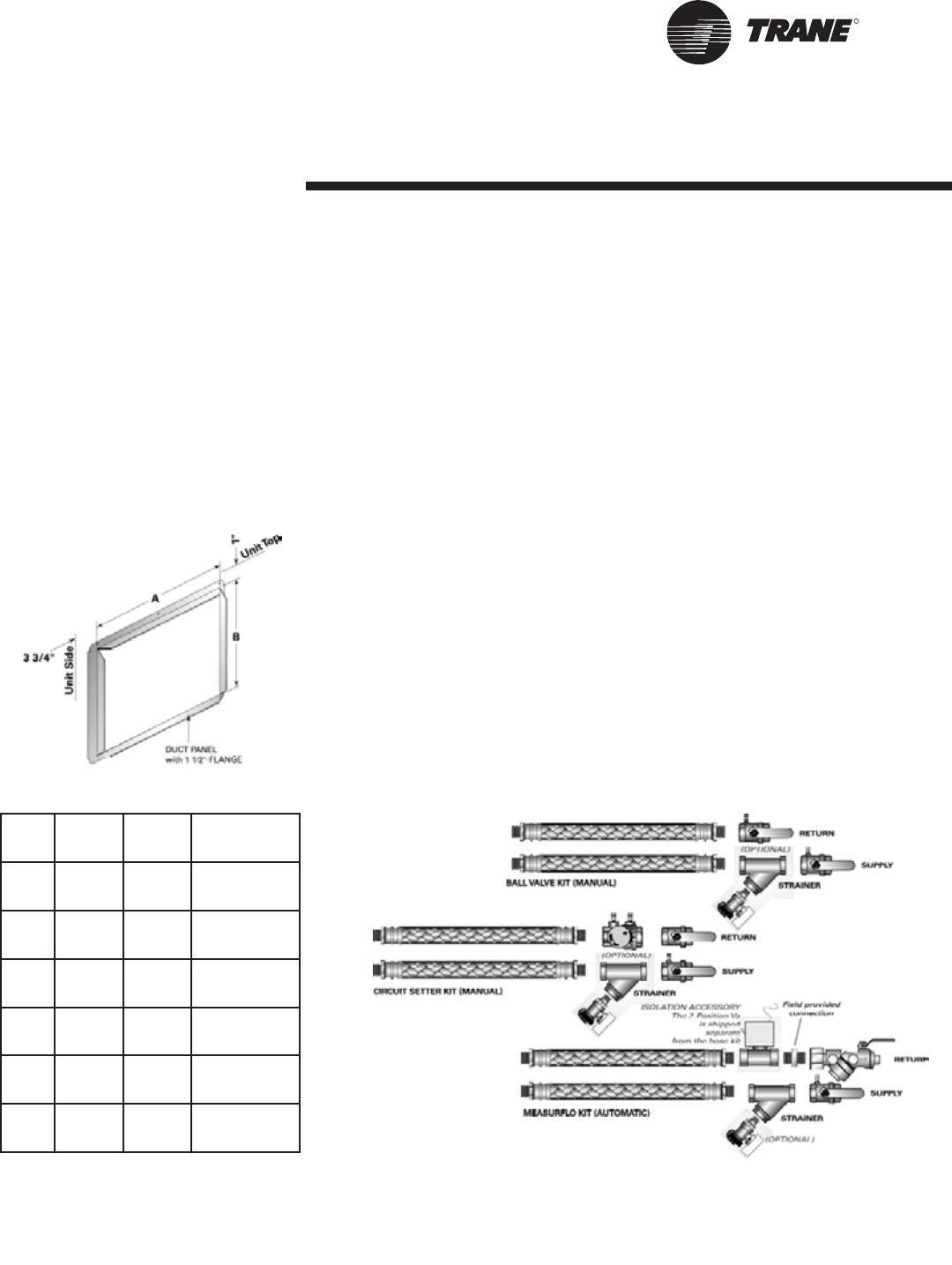
Hose Kits
Trane provides three hose kit selections for equipment balancing.
• Ball valve flow control (manual)
• Circuit setter flow control (manual)
• Automatic flow control (automatic)
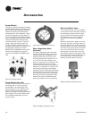
Each selection provides some accuracy in equipment balancing. Range of accuracy
consist of ±25% for the ball valve method, ±20% for the circuit setter method, and
±10% for the automatic flow control method.
Utilizing the ball valve method, the pressure/temperature measurement on the
leaving and entering side of the heat pump is measured within the water piping.
The ball valve is then throttled to change the amount of flow to the unit to reach
the desired temperature or pressure differential.
The circuit setter method combines both the readout and the adjustment feature in
one device. In order to determine flow rate, the user must record both handle posi-
tion, and differential pressure drop. Then, the user must consult a chart containing
both pieces of information to make the necessary adjustments to the circuit setter.
For automatic system balancing of a water-source heat pump, the Mesurflo® self
balancing kit provides a constant flow rate over the pressure differential rage of 2
to 80 psid. As system pressure changes (through further addition of heat pumps,
for example) each individual flow control valve will automatically adjust to the new
system conditions. In variable water volume applications, a self balancing hose kit
can provide continuous balancing because of its ability to automatically adjust to
the varying system conditions. For more information pertaining to the automatic
balancing hose kits, see literature
documentation WSHP-SLB005-EN.
Figure 42: System balancing hose kits.
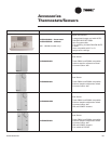
Unit
Size
A
(in/mm)
B
(in/mm)
Model
Number
006-
015
17-1/2
(445)
13
(330)
4474 1133 0100
018-
030
20-1/2
(521)
15
(381)
4474 1134 0100
036-
042
22-1/2
(572)
17
(432)
4474 1135 0100
048-
060
26-1/2
(673)
19
(483)
4474 1136 0100
150,
180
* * 4475 2119 0100
240 * * 4475 2121 0100