


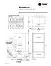
WSHP-SVX04A-EN 17
Connecting a Distributed Pump
Kit to a Closed Loop System
All piping external to the unit is the re-
sponsibility of the installer. The water
pipe installation must be done in ac-
cordance with local codes. If no local
code applies, national codes should be
followed. It is the contractor’s respon-
sibility to know and adhere to all appli-
cable codes.
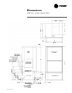
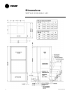
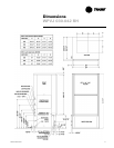
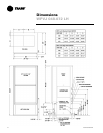
Water inlet and outlet to the unit’s wa-
ter-to-refrigerant heat exchanger are
clearly marked on the submittal draw-
ings found on pages 7 through 13. The
supply and return piping must be in-
stalled correctly to the unit to ensure
the safety devices will work properly.
Units that are not piped accordingly
will not obtain the manufacturers war-
ranty.
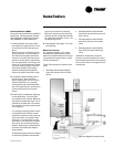
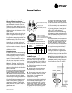
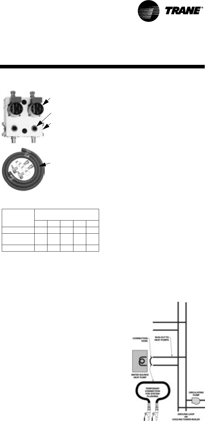
A pump module and hose kit (Figure 5)
may be used to connect the unit to
closed loop piping.
Using Antifreeze
In areas of the country where entering
water temperatures drop below 45°F
or where piping is being run through
areas subject to freezing, the loop
must be freeze protected by using an
approved antifreeze solution to pre-
vent the earth loop water from freez-
ing inside the heat exchanger.
Methanol, Ethylene, and Propylene
Glycol are the most commonly used
antifreeze solutions. Consult your geo-
thermal unit supplier for the best solu-
tions in your area.
Propylene glycol is not recommended
in installations where the water tem-
perature are expected to fall below
30°F. At extreme temperatures, the vis-
cosity increases to the point where
normal loop circulating pumps cannot
maintain proper flow.
Calculate the approximate volume of
water in the system by using the re-
quirements detailed in Table 2. Add
three gallons to this total to allow for
the water contained in the hose kit and
geothermal unit.
Table 2: Required Antifreeze by volume
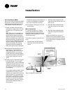
Cleaning and Flushing
the Water Loop
After the piping system is complete,
cleaning and flushing the water loop
should be done to avoid trash settle-
out in the condenser (Figure 6). An ex-
tra pipe may be necessary to connect
the hose kits.
1 Electrical power to the unit should
be disconnected.
2 Double back the supply hose and
connect directly to the return riser
valve.
3 Fill the water system with clean wa-
ter using the water make up connec-
tions. Note: Air vents should be
opened during filling.
4 With the air vents closed, start the
circulating pump and then crack the air
vents to bleed off the trapped air, as-
suring circulation through all compo-
nents of the system. Note: Make up
water must be available to the system
to replace the volume formerly occu-
pied by the air that is bled off.
Type of
Antifreeze
Minimum Temperature for
Freeze Protection
10°F 15°F 20°F 25°F 30°F
Methanol 25% 21% 16% 10% 3%
Propylene
Glycol
23% 21% 19% 9% 6%
Ethylene Glycol 20% 19% 16% 14% 12%
5 With the air vented and the water
circulating, the entire system should
be checked for leaks with repairs made
as required.
6 Check and adjust the water/air level
in the expansion tank.
7 Operate the boiler (if used) by rais-
ing the loop temperature to approxi-
mately 85°F. Make checks per
manufacturer’s instructions. During
this operation, visual checks should be
made for leaks that may have occurred
due to increased heat. Repair as re-
quired.
8 Open the system at the lowest point
for the initial blow down (making sure
the make up water is equal to the wa-
ter being dumped). Continue blow
down until the water leaving the drain
runs clear, but not less than 2 hours.
9 Shut down pumps and boiler (if
used). Reconnect the hoses to the
proper supply/return for each unit,
placing the water-to-refrigerant heat
exchanger in the water circulating sys-
tem. Note: Vents should be open when
the pumps and boiler are shut down.
10 Refill the system and bleed off any
air. Add antifreeze to the system in cli-
mates where ambient temperature
falls below freezing, using the propor-
tion of antifreeze shown in Table 2.
Installation
From Units
W.O.
To Units
W.I.
Bronze or Cast Iron Pump
Purging Cap (2)
Shut-off 3-way Valve (2)
1" MPT x barb fittings
1" MPT x barb elbows with
pressure temperature ports
and 10’ of rubber hose with
4 hose clamps
Figure 5: Pump module and hose kit
Figure 6: System flushing