


14 WSHP-SVX04A-EN
General Installation Checks
The checklist below is a summary of
the steps required to successfully in-
stall a unit. This checklist is intended to
acquaint the installing personnel with
procedures required in the installation
process. It does not replace the de-
tailed instructions called out in the ap-
plicable sections of this manual.
1 Remove packaging and inspect the
unit. Check the unit for shipping
damage and material shortage; file
a freight claim and notify appropri-
ate sales representation.
Note: The vertical units have been
tied to the skid by (8) shipping
brackets with (16) 5/16" screws.
Remove the (8) screws attached on
the unit side, and (2) screws at-
tached at the L bracket side. The
unit may now be slid off of the
skid. Re-attach (8) of the screws
into the unit base pan.
2 Verify the correct model, options
and voltage from the unit name-
plate.
3 Verify the installation location of
the unit will provide the required
clearance for proper operation.
4 Remove refrigeration access panel
and inspect the unit. Be certain the
refrigerant tubing has clearance
from adjacent parts.
WARNING
Hazardous
Voltage!
Disconnect all electric power,
including remote disconnects
before servicing. Follow proper
lockout/tagout procedures to
ensure the power can not be
inadvertently energized. Failure to
disconnect power before
servicing could result in death or
serious injury.
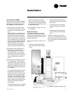
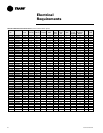
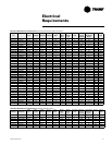
Main Electrical
5 Verify the power supply complies
with the unit nameplate specifica-
tions.
6 Inspect all control panel compo-
nents; tighten any loose connec-
tions.
7 Connect properly sized and pro-
tected power supply wiring to a
field-supplied/installed disconnect
switch and to the unit contactor
(1K1) in the unit’s cabinet control
box for equipment.
8 Install proper grounding wires to
an earth ground.
Note: All field-installed wiring must
comply with NEC and applicable local
codes.
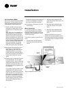
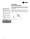
Low Voltage Wiring (AC & DC)
Requirements
9 Connect properly sized control wir-
ing to the proper termination
points between the thermostat/
sensor and the terminal board in
the unit’s control box.
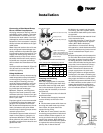
Filter Installation
10 Each unit ships with 1" filters. Do
not operate the unit without fil-
ters.
Installation