


16 WSHP-SVX04A-EN
Unit Installation; WPHF
Duct collars are provided for the WPHF
equipment. The duct system and dif-
fusers should be sized inaccordance
with ASHRAE or ACCA Manual D.
1 Install a flexible connector (field
provided) for supply/return air duct
connections on all metal duct sys-
tems.
Note: If the unit is connected to ex-
isting ductwork, an initial check of
the mechanical system should be
made to insure the duct has the ca-
pacity to handle the air required for
the unit application. If ducting is too
small, as in the replacement of heat-
ing only systems, larger ductwork
should be installed. All existing
ductwork should be checked for
leaks, and repairs should be made.
2 Insulate the field ductwork with a
minimum of 1" duct insulation.
Note: Installing the unit to an unin-
sulated ductwork in an uncondi-
tioned space may adversely affect
the unit’s performance, as well as in-
crease noise emissions into the
space.
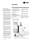
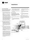
3 Install proper condensate trapping
to the equipment. The unit drain
connection is 3/4" (19mm). When de-
signing the condensate trap, it is im-
portant to consider the unit’s draw-
thru design requiring negative pres-
sure trapping.
In a properly trapping system, when
condensate forms during normal
operation, the water level in the trap
rises until there is a constant flow
(Figure 4). It is imperative to main-
tain water in the trap and not allow
the trap to dry out during heating
season. Keeping the trap primed at
all times will enable the water to
flow properly.
Condensate piping must be installed
to allow the cleanable condensate
pan to be removed for cleaning.
4 Flush System. See page 17 for sys-
tem flushing.
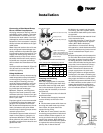
Water Connection
For vibration isolation, it is recom-
mended that flexible steel braided
hoses be installed instead of hard pip-
ing between the supply/return risers
and the equipment.
Trane offers 4-types of hose kit varia-
tions:
• Stainless steel braided flexible
hose with manual shut-off (ball)
valves
• Stainless steel braided flexible
hose with manual deluxe shut-off
(ball) valves
• Stainless steel braided flexible
hose with manual circuit-setter
valve
• Stainless steel braided flexible
hose with automatic balancing
valve
Additional accessories, such as a
strainer are recommended for use to
eliminate contaminants from entering
the co-axial water-to-refrigerant heat
exchangers.
Installation
Figure 4: Negative pressure trap