


18-CD19D6-32 29
Installer’s Guide
ELECTRICAL CONNECTIONS
Make wiring connections to the unit as indicated on en-
closed wiring diagram. As with all gas appliances using
electrical power, this furnace shall be connected into a
permanently live electric circuit. It is recommended
that furnace be provided with a separate “circuit protec-
tion device” in the electric circuit. The furnace must be
electrically grounded in accordance with local codes or
in the absence of local codes with the National Electri-
cal Code, ANSI/NFPA 70 or CSA C22.1 Electrical Code,
if an external electrical source is utilized.
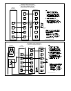
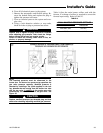
OUTDOOR UNIT
(NO TRANSFORMER)
SEE
NOTE 6
From drawing B340388 Rv 2
SEE
NOTE 8
FURNACE
B/C
B/C
TO 115 V 1 PH.,
60 HZ., POWER
SUPPLY PER
LOCAL CODES
HUM SEE
NOTE 5
EAC SEE
NOTE 5
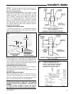
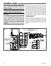
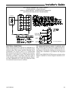
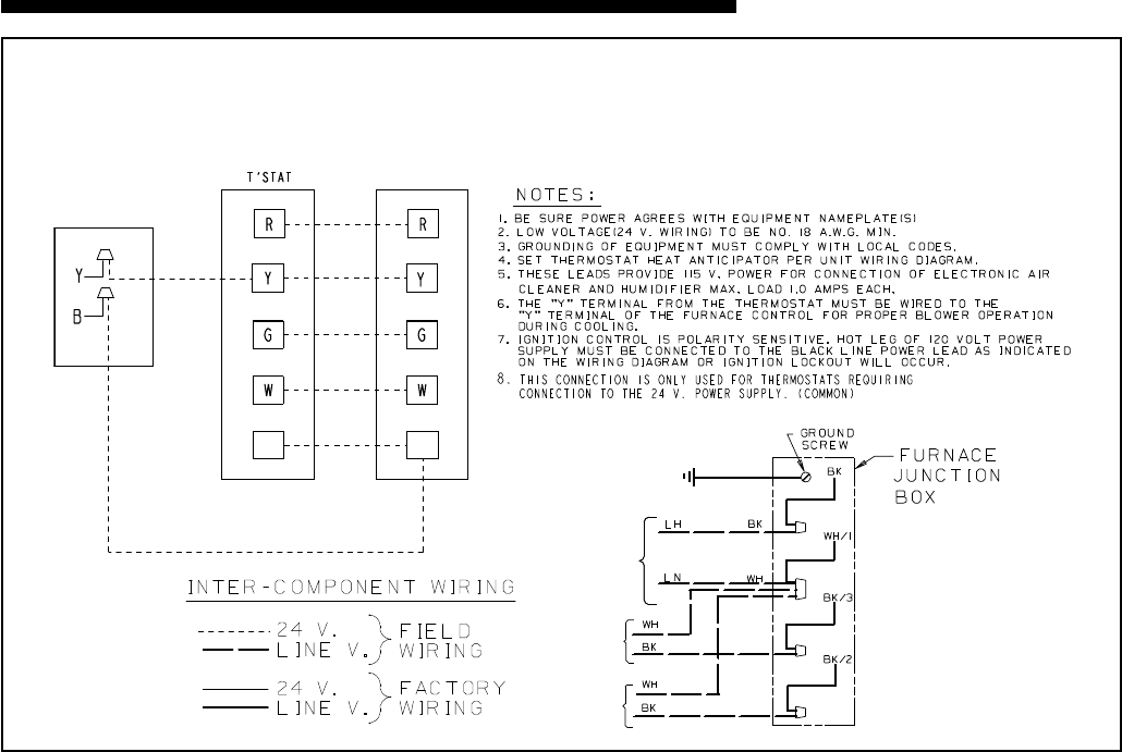
FIELD WIRING DIAGRAM FOR 1 STAGE FURNACE
1 STAGE HEATING, 1 STAGE COOLING
USING A 1 STAGE HEATING, 1 STAGE COOLING THERMOSTAT
(OUTDOOR SECTION WITHOUT TRANSFORMER)
The integrated furnace control is polarity sensi-
tive. The hot leg of the 120V power supply must be con-
nected to the black power lead as indicated on the wir-
ing diagram. Provision for hooking up an electronic air
cleaner and or humidifier is provided on the integrated
control.
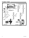
Refer to the SERVICE FACTS literature and unit wiring
diagram attached to furnace diagram attached to fur-
nace.