


18-CD19D6-32 17
Installer’s Guide
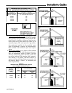
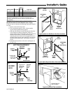
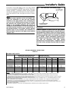
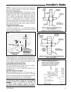
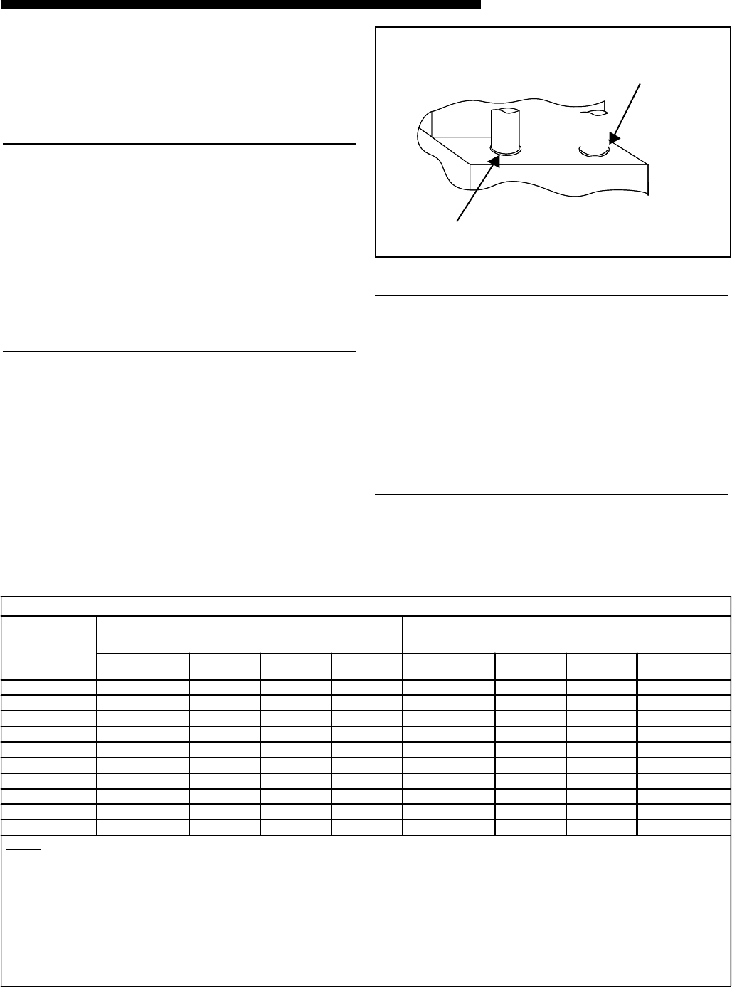
Seal VENT PIPE
with RTV sealant
Seal INLET AIR PIPE
with RTV sealant
Front of Furnace
VENT AND INLET AIR CONNECTIONS
g
Connection of the vent pipe to the vent collar should
also be accomplished using RTV type sealant. This type
sealant provides a connection which remains flexible
and can be separated in the future if service needs re-
quire the removal of the vent pipe for service or clear-
ance.
NOTE:
To ensure proper operation at the vent lengths indi-
cated, the combustion air inlet and vent terminals
should be in the same pressure zone. Terminating the
vent and inlet in different pressure zones will change
the maximum vent lengths and may cause nuisance
tripping of the pressure switch(es). The amount of
change can not be predicted. The selection of the inlet
and outlet terminal locations are the responsibility of
the designer/installer. If the installer chooses separate
pressure zones for the terminals, the combustion air
inlet termination must be in the higher (more positive)
pressure zone.
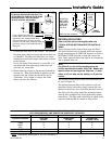
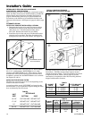
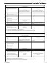
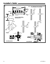
MAXIMUM VENT LENGTH:
MODEL
DIRECT VENT (2 PIPE SYSTEM) -
MAXIMUM TOTAL EQUIVALENT FEET FOR
VENT AND INLET AIR PIPES (See Notes)
NONDIRECT VENT (1 PIPE SYSTEM) -MAXIMUM TOTAL
EQUIVALENT FEET FOR
VENT PIPE ONLY (See Notes)
2" PIPE
& FITTINGS
2-1/2" PIPE
& FITTINGS
3" PIPE
& FITTINGS
4" PIPE
& FITTINGS
2" PIPE
& FITTINGS
2-1/2" PIPE
& FITTINGS
3" PIPE
& FITTINGS
4" PIPE
& FITTINGS
*UX1B040A9241A
60 80 100 130 50 80 80 130
*UX1B0
60A9241A
60 80 100 130 50 80 80 130
*UX1B060A9361A
60 80 100 130 50 80 80 130
*UX1B080A9241A
50 80 100 130 40 80 80 130
*UX1B080A9421A
50 80 100 130 40 80 80 130
*UX1C080A9601A
NOT ALLOWED 60 100 130 NOT ALLOWED 60 80 130
*UX1C100A9361A
NOT ALLOWED 40 100 130 NOT ALLOWED 40 80 130
*UX1C100A9481A
NOT ALLOWED 40 100 130 NOT ALLOWED 40 80 130
*UX1D100A9601A
NOT ALLOWED 40 100 130 NOT ALLOWED 40 80 130
*UX1D120A9601A
NOT ALLOWED 15 60 130 NOT ALLOWED 25 70 130
NOTES: * - First letter may be "A" or "T"
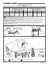
1. The INLET AIR of one pipe systems require the installation of a 90° elbow (to prevent dust and debris from falling straight into thefurnace) and a 2 foot
horizontal or vertical straight pipe section connected before or after the elbow.
2. DO NOT MIX PIPE DIAMETERS IN THE SAME LENGTH OF PIPE OUTSIDE THE FURNACE CABINET (Except adapters at the top of the furnace).
If different inlet and vent pipe sizes are used, the vent pipe must adhere to the maximum length limit shown in the table above (See Note 7 below for exception).
The inlet pipe can be of a larger diameter, but never smaller than the vent pipe.
3. MAXIMUM PIPE LENGTHS MUST NOT BE EXCEEDED! THE LENGTH SHOWN IS NOT A COMBINED TOTAL, IT IS THE MAXIMUM LENGTH OF EACH
(Vent or Inlet air pipes in two pipe systems).
4. One standard radius 90° elbow is equivalent to 12' of 4" pipe; one SHORT radius 90° elbow is equivalent to 10' of 3" pipe and one LONG radius elbow is
equivalent to 6' of 3" pipe. One SHORT/LONG radius 90° elbow is equivalent to 7½' of 2½" pipe, & 5' of 2" pipe. Two 45° elbows equal one 90°elbow.
5. The termination tee or bend must be included in the total number of elbows. If the BAYVENT100 termination kit is used, the equivalent length of pipe is 5 feet.
There is zero equivalent length for the BAYVENT200.
6. Pipe adapters are field supplied.
7. 4" pipe may be reduced to 3" for termination with BAYAIR30AVENTA or BAYVENT200 without additional length restriction.
UPFLOW/ HORIZONTAL VENTING TABLE
TABLE 10
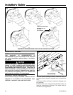
IMPORTANT:
Products installed in Canada must use vent systems
that are certified to the Standard for Type BH Gas Vent-
ing Systems (ULC S636) for Class II-A venting systems
(up to 65°C). Components of the vent system must not
be interchanged with other vent systems or unlisted
pipe or fittings. Plastic components, specified prim-
ers, and glues must be from a single system manufac-
turer and not intermixed with other system
manufacturer's vent system parts. In addition, the first
three feet of the vent pipe must be visible for inspec-
tion.