


18-CD19D6-32 27
Installer’s Guide
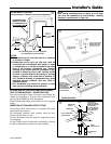
HORIZONTAL APPLICATIONS
Upflow and Downflow furnaces - All horizontal ap-
plications are left side only. It is always recommended
that the auxiliary drain pan be installed under a hori-
zontally installed evaporator and/or 90% gas furnace.
Connect the auxiliary drain pan to a separate drain line
(no trap is needed in this line).
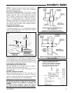
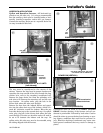
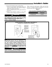
The trap must be repositioned to the exterior of the
cabinet. Remove the trap from its present location and
reposition the trap outside of the unit, through the long
circular hole, next to the secondary recuperated cell.
Remove the larger drain line (from the secondary cell)
and trim to fit between the secondary cell and the new
trap location. On upflow units, plug the hole in the
blower deck where the tube went through.
Remove the hose from the induced blower and reposi-
tion into the other drain tap of the inducer, which is lo-
cated 90° clockwise around the inducer. Move the cap
from that drain tap to the unused drain tap. On upflow
units, plug the hole in the blower deck where the tube
went through. This tube on downflow units will need to
be cut to fit between the inducer and the trap. On
upflow units, this tube may need to be extended, using
the tubing shipped with the furnace.
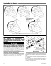
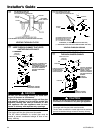
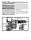
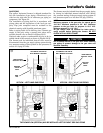
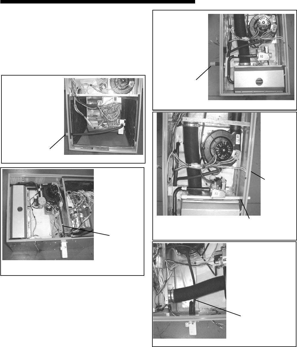
UPFLOW (VERTICAL)
Left side
Use
extension
hose here
UPFLOW HORIZONTAL 21" & 24" UNITS
(Left side only)
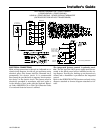
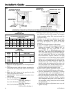
DOWNFLOW (VERTICAL)
Left
side
Use CPVC tubing from Trap outlet,
over burner box to cabinet exit
DOWNFLOW (VERTICAL)
Right
side
Cut off curved end of
Inducer drain hose
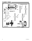
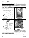
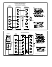
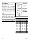
DOWNFLOW (HORIZONTAL)
Connections must be made to an OPEN/ VENTED
DRAIN. Outdoor draining of the furnace and coil con-
densate is permissible if allowed by local codes. Caution
should be taken to prevent drains from freezing or caus-
ing slippery conditions that could lead to personal in-
jury. Excessive draining of condensate may cause satu-
rated ground conditions that may result in damage to
plants.
&
*
(
)
Q