


18-CD19D6-32 15
Installer’s Guide
GENERAL VENTING
The following steps shall be followed with each appli-
ance remaining connected to the common venting sys-
tem placed in operation, while the other appliances re-
maining connected to the common venting system are
not in operation.
1. Seal any unused openings in the common venting
system.
2. Visually inspect the venting system for proper size
and horizontal pitch and determine there is no
blockage or restriction, leakage, corrosion or other
deficiencies which could cause an unsafe condition.
3. Insofar as is practical, close all building doors and
windows and all doors between the space in which
the appliances remaining connected to the common
venting system are located and other spaces of the
building. Turn on clothes dryers and any appliances
not connected to the common venting system. Turn
on any exhaust fans, such as range hoods and bath-
room exhausts, so they will operate at maximum
speed. Do not operate a summer exhaust fan, close
fireplace dampers.
4. Follow the lighting instructions. Place the appliance
being inspected in operation. Adjust thermostat so
appliance will operate continuously.
5. Test for spillage at the draft hood relief opening af-
ter 5 minutes of main burner operation. Use the
flame of a match or candle, or smoke from a ciga-
rette, cigar, or pipe.
6. After it has been determined that each appliance re-
maining connected to the common venting system
properly vents when tested as outlined above, re-
turn door, windows, exhaust fans, fireplace dampers
and any other gas-burning appliance to their previ-
ous conditions of use.
If improper venting is observed during any of the above
tests, the remaining common venting system must be
corrected. Correction of the remaining common vent
system should be done by referring to the latest edition
of the National Fuel Gas Code (ANSI Z223.1) • CAN/
CGA B149.1 Installation Codes or “Exhibit J” of
ANSI Z21.47 • CAN/ CGA-2.3 Standards. The following
are general steps to be used to correct or resize a re-
maining vent system when a furnace which may not be
common vented is removed from the system:
a. Determine the Btu per hour input of all remain-
ing appliances attached to the venting system.
b. Determine the diameter, rise, and lateral of the
existing venting system, as well as quantity and
type of bends.
c. Use the appropriate tables in the latest edition of
the National Fuel Gas Code (ANSI Z223.1 •
CAN/ CGA B149.1 Installation Codes or “Exhibit
J” of ANSI Z21.47 • CAN/ CGA-2.3 Standards.
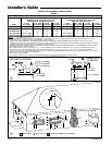
“Exhibit J” includes examples and drawings of
typical venting systems.
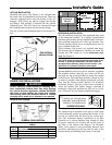
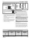
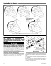
IMPORTANT:
These furnaces may be installed as Direct Vent (sealed
combustion) or as Nondirect vent (single pipe). The fur-
naces are shipped DIRECT VENT with sealed combus-
tion.
For DIRECT VENT APPLICATION: The furnaces must be
vented to the exterior of the house and combustion air
MUST come through the inlet air pipe FROM OUTSIDE
AIR.
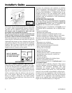
For NONDIRECT VENT APPLICATION: The furnace shall
be vented to the exterior of the house, but combustion air
may enter from the surrounding area as long as combus-
tion air requirements are met. (See AIR FOR COMBUS-
TION AND VENTILATION)
THIS FURNACE MUST BE VENTED TO THE OUT-
DOORS.
THESE FURNACES ARE INDUCED DRAFT VENTED
AND MUST NOT BE CONNECTED TO ANY VENT
SERVING ANOTHER APPLIANCE. PLEASE NOTE
THAT THESE FURNACES USE POSITIVE-
PRESSURE VENT SYSTEMS.
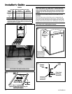
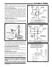
Proper venting is essential to obtain maximum effi-
ciency from a condensing furnace. Proper installation
of the vent system is necessary to assure drainage of
the condensate and prevent deterioration of the vent
system.
American Gas Association has certified the design of
condensing furnaces for a minimum of 0" clearance
from combustible materials with a single wall plastic
vent pipe.
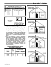
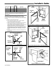
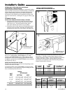
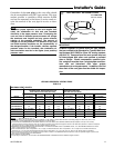
The recommended system is assembled from 2", 2-1/2",
or 3" plastic pipe and fittings (See Table 9, page 17).
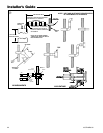
Where the system is routed to the outdoors through an
existing masonry chimney containing flue products
from another gas appliance, or where required by local
codes, then 3" venting of Type 29-4C stainless steel
must be used in place of PVC material.
These furnaces have been classified as CATEGORY IV
furnaces in accordance with the latest edition of
ANSI Z21.47 • CAN/ CGA-2.3 Standards. Category IV
furnaces operate with positive vent pressure and with a
vent gas temperature less than 140°F above the
dewpoint. These conditions require special venting sys-
tems, which must be gas tight and water tight.
NOTE:
When an existing furnace is removed from a venting
system serving other gas appliances, the venting sys-
tem is likely to be too large to properly vent
the re-
maining attached appliances.