


2 of 12
INSTALLATION OVERVIEW
1. Install the TZEMT400BB32MAA thermostats and wire HVAC according to standard Trane
TZEMT400BB32MAA documentation.
2. Test the thermostat and climate system to ensure that the thermostats correctly turn on the
appropriate heating or cooling equipment, and open or close the appropriate valves / dampers.
3. Install a Leviton VRC0P-1LW (+3) RS-232 Z-Wave adapter in a location convenient for both a serial
run to the g! Controller and within range of other Z-Wave devices.
Note: Be sure that the “+3” notation is present on the back of the VRC0P-1LW. (See the Leviton
application note for additional information: http://communities.leviton.com/docs/DOC-2392).
4. Run a Cat-5 or serial cable to the location of the Z-Wave RS-232 location.
5. Using a Primary Controller, such as a programming remote (ex. Leviton VRCPG), ControlThink’s
ThinkEssentials or Leviton’s Vizia RF+ Installer Tool (v1.1.0.0) create a Z-Wave network and add
thermostats and the RS-232 adapter according to standard procedures.
Important! Disconnect the g! system from the VRC0P controller when any Z-Wave network
configuration is occurring.
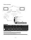
6. Connect the Serial Cabling to the Z-Wave RS-232 adapter electrically. See the wiring diagrams.
7. Configure g! for the thermostats and confirm communication between the thermostats and the g!
Controller.
8. Test the system by changing the set points, modes and schedules on the viewer and various
thermostats, confirming that the various components in the system respond as expected.
Z-W
AVE REPEATERS
Many Z-Wave devices function as repeaters, meaning an incoming signal can be passed to another Z-
Wave device within range. The maximum distance a signal can be sent from one Z-Wave device to
another varies depending on the brand/model of the device used. See the manufacturer’s
documentation for the devices you intend to use for specifics.
The signal can be extended from the controller to the device being controlled by a maximum of four
passes, known as “hops.” (From the controller to the first device, the first device to the second, the
second device to the third and from the third device to the one actually being sent the signal.)
Depending on the network configuration, occasionally it may be necessary to manually program the
“hops” to optimize reliability. Refer to the documentation that came with your specific programming
tool for details.
Note: Because Z-Wave door locks require repeaters that are “beaming-compatible” and that support
beaming of encrypted signals we recommend using only repeaters (lamp modules, switches, etc.) that
support these features if door locks will be a part of the installation. See the manufacturer’s
documentation for the devices you intend to use for specifics.
N
OTES REGARDING THE TRACKING OF Z-WAVE DEVICES:
In general g! keeps track of the states of all of the Z-Wave Network Devices; however there is latency in
the reporting back of the devices from the Z-Wave network. The result is that g! updates its states as the
devices report back. This is evident when watching the viewer interface after a change is made at the
device. The viewer controls will update sequentially over a few seconds (or more on larger systems) as
the devices report their states.