


TRG-TRC014-EN 57
period four
Fan Modulation
notes
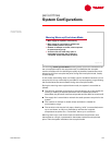
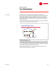
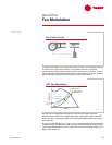
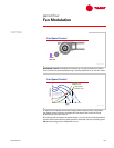
To achieve this balance, a simple control loop is used. First, the static pressure
is sensed from a particular location in the system. Second, a controller
compares this static pressure reading and the set point of the system. Finally,
the fan capacity is controlled to deliver the required airflow, at a static pressure
that maintains this set point at the location of the system sensor.
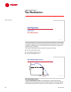
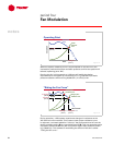
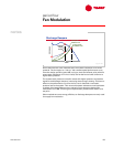
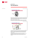
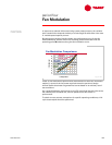
We will use an exaggerated example to illustrate this system operation.
Assume that the load on the system decreases, causing all or part of the VAV
terminal units to modulate closed. This causes the system resistance curve to
shift upwards.
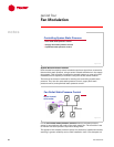
In response, the fan begins to “ride up” the constant-speed performance curve
from the design operating point (A), trying to reach the balance point with this
new system resistance curve. As a result, the fan delivers a lower airflow at a
higher static pressure.
Fan Control Loop
static
static
-
-
pressure
pressure
sensor
sensor
controller
controller
supply
supply
fan
fan
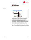
Figure 78
VAV Fan Modulation
sensor
sensor
set point
set point
VAV system
VAV system
modulation curve
modulation curve
airflow
airflow
static pressure
static pressure
A
design system
design system
resistance curve
resistance curve
actual system
actual system
resistance curve
resistance curve
B
Figure 79