


54 TRG-TRC014-EN
notes
period four
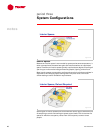
Fan Modulation
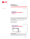
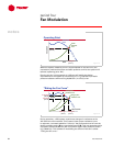
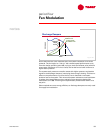
When the system resistance curve is superimposed on the fan curve, the
intersection predicts the airflow and static pressure at which the system will
balance (operating point “A”).
Running the fan in this example at 1,000 rpm will satisfy the design
requirements of the system by overcoming 2.7 in. H
2
O [672.5 Pa] of static
pressure resistance while moving 24,000 cfm [11.3 m
3
/s] of air.
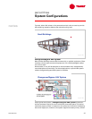
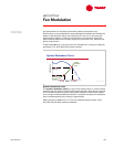
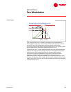
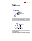
During operation, a VAV system experiences changes in resistance as the
VAV terminal units modulate. This creates a new system resistance curve.
In response, a constant-speed fan “rides up” the performance curve from the
design operating point (A) to a new balance point (B). This new operating point
is at lower airflow (18,000 cfm [8.5 m
3
/s]) and a higher static pressure (3.15 in.
H
2
O [784.6 Pa]). This method of modulating the airflow of the fan is called
“riding the fan curve.”
Operating Point
A
airflow
airflow
static pressure
static pressure
24,000 cfm
24,000 cfm
[11.3 m
[11.3 m
3
3
/s]
/s]
2.7 in. H
2.7 in. H
2
2
O
O
[672.5 Pa]
[672.5 Pa]
system
resistance
curve
system
system
resistance
resistance
curve
curve
1
,
0
0
0
r
p
m
1
,
0
0
0
r
p
m
performance
curve
performance
performance
curve
curve
Figure 74
"Riding the Fan Curve"
A
24,000 cfm
24,000 cfm
[11.3 m
[11.3 m
3
3
/s]
/s]
2.7 in. H
2.7 in. H
2
2
O
O
[672.5 Pa]
[672.5 Pa]
1
,
0
0
0
r
p
m
1
,
0
0
0
r
p
m
design system
resistance curve
design system
design system
resistance curve
resistance curve
actual system
resistance curve
actual system
actual system
resistance curve
resistance curve
static pressure
static pressure
increase
increase
airflow reduction
airflow reduction
3.15 in. H
3.15 in. H
2
2
O
O
[784.6 Pa]
[784.6 Pa]
18,000 cfm
18,000 cfm
[8.5 m
[8.5 m
3
3
/s]
/s]
B
Figure 75