


18 TRG-TRC012-EN
notes
period two
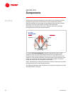
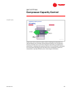
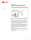
Refrigeration Cycle
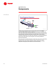
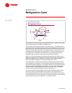
The theoretical vapor-compression refrigeration cycle for a helical-rotary water
chiller can be plotted on a pressure-enthalpy chart.
The refrigerant leaves the evaporator as saturated vapor ➀ and flows to the
suction end of the compressor where it enters the compartment for the suction-
gas-cooled motor. Here the refrigerant flows across and cools the motor, then
enters the compression chamber. The refrigerant vapor is compressed in the
compressor to a high pressure and temperature ➁. Energy input to the motor
and compressor is imparted to the refrigerant as superheat. Superheated
refrigerant vapor leaves the compressor and enters the condenser.
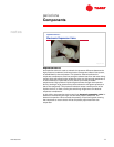
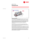
Water or air flowing through the condenser absorbs heat from the hot, high-
pressure refrigerant. This reduction in the heat content of the refrigerant vapor
causes it to desuperheat ➂, condense into liquid ➃, and further sub-cool ➄
before leaving the condenser to travel to the expansion device.
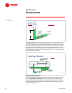
The pressure drop created by the expansion process causes a portion of the
liquid refrigerant to evaporate. The evaporating refrigerant absorbs heat from
the remaining liquid refrigerant. The resulting mixture of cold liquid and vapor
refrigerant enters the liquid/vapor separator ➅. Here the vapor is separated
from the mixture and routed directly to the suction side of the compressor ➀
and the remaining liquid refrigerant enters the evaporator ➆.
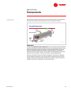
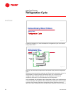
The cool low-pressure liquid refrigerant enters the distribution system in the
evaporator shell and is distributed over the tubes in the evaporator tube
bundle, absorbing heat from water that flows through the tubes. This transfer
of heat boils the film of liquid refrigerant on the tube surfaces and the resulting
vapor is drawn back to the compressor ➀ to repeat the cycle.
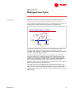
helical-rotary water chiller
Refrigeration Cycle
6
6
pressure
pressure
enthalpy
enthalpy
evaporator
evaporator
1
1
2
2
5
5
7
7
condenser
condenser
compressor
compressor
expansion
expansion
device
device
liquid/vapor
liquid/vapor
separator
separator
4
4
3
3
Figure 28