


18 PKG-SVX14A-EN
mechanical
requirementsInstallation
Refrigerant Piping (Air-Cooled
Units Only)
Reference industry recommendations
for air-cooled unit refrigerant piping. If
suspending piping from the building, use
isolation hangers to prevent vibration
transmission.
Air-cooled units ship with a holding
charge of nitrogen. Before installing unit
piping, momentarily depress either the
suction or discharge line access valve to
verify that the holding charge has not
been lost. If nitrogen does not escape
when depressing the access valve, leak-
test the entire refrigerant system to
determine the source of loss.
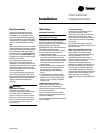
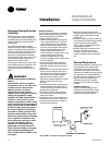
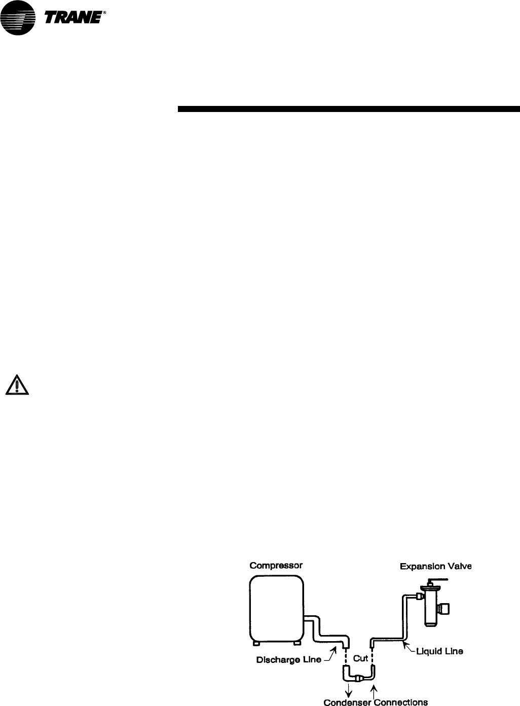
The charge is contained by a continuous
loop of both hot gas and liquid lines. You
must cut the loop for connection to
discharge and liquid lines. See Figure I-
MR-1.
Brazing Procedures
Proper brazing techniques are essential
when installing refrigerant piping. Keep
the following factors in mind when
making sweat connections.
1. When heating copper in the presence
of air, copper oxide forms. To prevent
copper oxide from forming inside the
tubing during brazing, sweep an inert
gas, such as dry nitrogen, through the
tubing. Nitrogen displaces air in the
tubing and prevents oxidation of
interior surfaces. A nitrogen flow of one
to three cubic feet per minute is
sufficient to displace the air. Use a
pressure regulating valve or flow meter
to control the flow.
2. Ensure tubing surfaces that require
brazing are clean and the ends of the
tubes are carefully reamed to remove
any burrs.
3. Make sure the inner and outer tubes of
the joint are symmetrical and have a
close clearance, providing an easy slip
fit. If the joint is too loose, the tensile
strength of the connection will be
significantly reduced. Make the overlap
distance equal to the inner tube
diameter.
4. Wrap the body of each refrigerant line
component with a wet cloth to keep it
cool during brazing. Excessive heat can
damage the components.
5. If using flux, apply it sparingly to the
joint. Excess flux will contaminate the
refrigerant system.
6. Apply heat evenly over the length and
circumference of the joint, making sure
the entire joint becomes hot enough to
melt the brazing material.
7. Begin brazing when the joint is hot
enough to melt the brazing rod. The hot
copper tubing, not the flame, should
melt the rod.
8. Continue to apply heat around the joint
circumference until the brazing material
is drawn into the joint by capillary
action, making a mechanically sound
and gas-tight connection.
9. Visually inspect the connection after
brazing to locate any pin holes or
crevices in the joint. Use a mirror to
inspect connections that are difficult to
see.
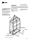
Figure I-MR-1. Air-cooled unit refrigerant piping
WARNING:
Hazard of Explosion and Deadly
Gases!
Never solder, braze or weld on
refrigerant lines or any unit com-
ponents that are above atmo-
spheric pressure or where
refrigerant may be present.
Always remove refrigerant by fol-
lowing the guidelines estab-
lished by the EPA Federal Clean
Air Act or other state or local
codes as appropriate. After refrig-
erant removal, use dry nitrogen to
bring system back to atmospheric
pressure before opening system
for repairs. Mixtures of refriger-
ants and air under pressure may
become combustible in the pres-
ence of an ignition source leading
to an explosion. Excessive heat
from soldering, brazing or weld-
ing with refrigerant vapors
present can form highly toxic
gases and extremely corrosive
acids. Failure to follow all proper
safe refrigerant handling prac-
tices could result in death or seri-
ous injury.
Electrical Requirements
Follow these guidelines, referring to unit
wiring diagrams and supply power
dimensional information to ensure
correct electrical requirements at the
installation site. Reference supply power
wiring locations on unit submittals orin
the “Dimensions and Weights” section.
Specific unit wiring diagrams are
provided on each unit. Use these
diagrams for connections or trouble
analysis.
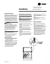
Unit Wiring Diagrams
Specific unit wiring diagrams are
provided on the inside of the control
panel door. Use these diagrams for
connections or trouble analysis.