


SXIH-SVX01B-EN 17
Installation
Installation
Procedure
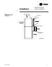
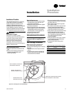
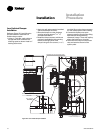
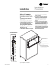
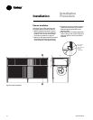
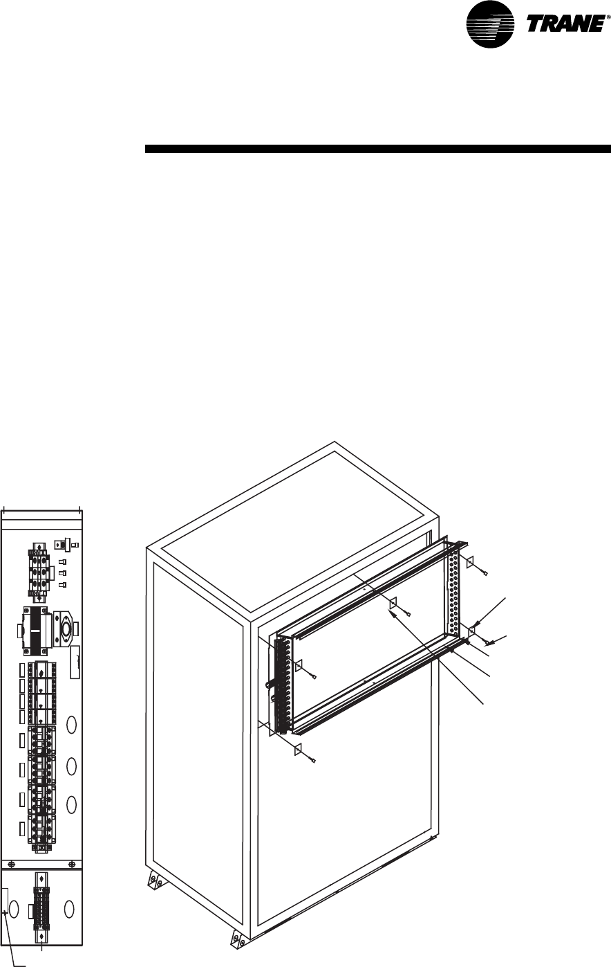
Figure I-IP-3. Hydronic coil installation
Hydronic Coil Installation
Reference Figure I-IP-3 and follow the
procedure below to install the hydronic
coil.
1. Remove the front grill, filters, two
upper frame screws, and two lower
frame screws.
2. Install the hydronic coil in the space
previously occupied by the grill.
3. Use the frame screws and one of the
grill screws to clamp the coil end
supports between the unit frame and
the mounting brackets (supplied with
the coil).
4. Slide the filters in the filter rack from
either end of the coil.
5. Adjust the filter rack for 2-inch filters by
removing the upper and lower filter
support brackets.
6. The hydronic coil can be installed for
either right or left-hand connections.
However, steam coils must have the
condensate lines connected to the
bottom outlet, with the top outlet
capped.
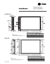
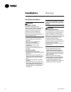
7. A heating coil control relay is factory
provided to use with BAY28X182 and
BAY28X183 thermostats. Drill two
5
/
32
”
holes
7
/
16
” apart and mount the relay in
the unit control box as shown in the
detail drawing below. Use a 6-32X.31
screw (not included) to mount the relay.
Connect wiring in accordance with the
thermostat wiring diagram.
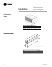
CONTROL BOX DETAIL
MOUNTING BRACKET (5)
FRAME SCREW (5)
FILTER SUPPORT BRACKET (2)
FILTER RACK
CENTER MOUNTING BRACKET
(USE GRILL MOUTING SCREW ON
7.5, 10, & 15-TON UNITS)
RC
Y1
Y1
Y2
Y2G
Y2
Y2
Y1
Y1C GR
21 3
3
12
LITTLEFUSE
600V (CS A)
FLQ 1/10
500V (UL)
FUSE 1 A
SR T
GND
GND
HVT
LVT
C4 C1C2C3 TR4TR3TR1 TR2
TNS
FC1
RELA
Y