


SXIH-SVX01B-EN 13
Installation
electrical
requirements
WARNING
Ground Wire!
All field-installed wiring must be
completed by qualified personnel. All
field-installed wiring must comply
with NEC and applicable local codes.
Failure to follow this instruction could
result in death or serious injury.
WARNING
Grounding Required!
Follow proper local and state electrical
code on requirements for grounding.
Failure to follow code could result in
death or serious injury.
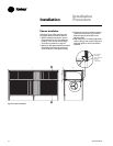
Electrical Requirements
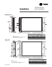
Follow these guidelines, referring to unit
wiring diagrams and supply power
dimensional information to ensure
correct electrical requirements at the
installation site. Reference supply power
wiring locations on unit submittals or in
the “Dimensions and Weights” section.
Specific unit wiring diagrams are
provided on each unit. Use these
diagrams for connections or trouble
analysis.
WARNING
Hazardous voltage!
Disconnect all electric power,
including remote disconnects before
servicing. Follow proper lockout/
tagout procedures to ensure the
power can not be inadvertently
energized. Failure to disconnect
power before servicing could result in
death or serious injury.
Supply Power Wiring
It is the installer’s responsibility to
provide power supply wiring to the unit.
Wiring should conform to NEC and all
applicable code requirements. To ensure
the unit supply power wiring is properly
sized and installed, follow the guidelines
below:
1. Verify the power supply available is
compatible with the unit nameplate
ratings. The supply power must be
within 10% of the rated voltage listed
on the unit nameplate.
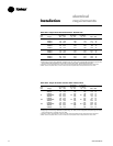
2. Reference the electrical data in Table I-
ED-1. Protect the electrical service from
over current and short circuit
conditions in accordance with NEC
requirements. Size protection devices
according to the electrical date on the
unit nameplate.
3. If using a field-supplied disconnect,
install it at or near the unit in
accordance with NEC. Do not mount a
field-supplied disconnect on the unit.
Reference the electrical service
entrance location on unit submittals.
4. Complete the unit power wiring
connections onto either the main
terminal block or the field-provided
non-fused disconnect switch.
5. Provide proper unit grounding in
accordance with local and national
codes.
Electrical Data Calculations
RLA = Rated Load Amps
Compressor LRA = Locked Rotor Amps
Fan Motor LRA = Locked Rotor Amps,
N.E.C. Table 430 - 151
FLA = Full Load Amps, N.E.C.
Table 430 - 150
Voltage utilization range is ±10 percent
Determination of Minimum Circuit
Ampacity (MCA)
MCA = 1.25 x largest motor amps (FLA
or RLA) + the sum of the remaining
motor amps.
Determination of Maximum Fuse Size
(MFS)
MFS = 2.25 x largest motor amps (FLA or
RLA) + the sum of the remaining motor
amps.
If the rating value determined does not
equal a standard current rating of over
current protective device, use the next
lower standard rating for the marked
maximum rating.
WARNING
Live electrical components!
During installation, testing, servicing
and troubleshooting of this product, it
may be necessary to work with live
electrical components. Have a
qualified licensed electrician or other
individual who has been properly
trained in handling live electrical
components perform these tasks.
Failure to follow all electrical safety
precautions when exposed to live
electrical components could result in
death or serious injury.
Voltage Imbalance
Voltage imbalance on three-phase
systems can cause motor overheating
and premature failure. Maximum
allowable imbalance is 2.0%, and the
readings used to determine it must be
measured at the compressor terminals.
Voltage imbalance is defined as 100 times
the sum of the division of the three
voltages from the average voltage. If, for
example, the three measured voltages
are 221, 230, 227, the average would be:
(221+230+227) = 226 volts
3
The percentage of voltage imbalance is
then:
100*(226-221) = 2.2%
226
In this example, 2.2 percent imbalance of
more than 2.0 percent exists, be sure to
check the voltage at the unit disconnect
and terminal block switch. If an imbalance
at the unit disconnect switch does not
exceed 2.0 percent, the imbalance is
caused by faulty wiring within the unit. Be
sure to conduct a thorough inspection of
the unit electrical wiring connections to
locate the fault, and make any repairs
necessary.