


RT-PRC007-EN30
Controls
the requirement, the UCP will energize
the second stage electric heat
contactor(s) if the appropriate limits are
closed. The UCP will cycle second stage
on and off as required while keeping
stage one energized.
The supply fan is energized
approximately 1 second before the
electric heat contactors. When the space
temperature rises above the heating
setpoint, the UCP deenergizes the supply
fan and all electric heat contactors.
Supply Air Tempering
This feature is available only with
TRACER® or with systems using
programmable zone sensors (CV only
with economizer). For gas and electric
heat units in the Heat mode but not
actively heating, if the supply air
temperature drops to 10 F below the
occupied zone heating temperature
setpoint, one stage of heat will be
brought on to maintain a minimum
supply air temperature. The heat stage is
dropped if the supply air temperature
rises to 10 F above the occupied zone
heating temperature setpoint.
Auto Changeover
When the System Mode is “Auto,” the
mode will change to cooling or heating
as necessary to satisfy the zone cooling
and heating setpoints. The zone cooling
and heating setpoints can be as close as
2 F apart.
Unoccupied Zone Temperature Control
Cooling and Heating
Both cooling or heating modes can be
selected to maintain Unoccupied zone
temperature setpoints. For Unoccupied
periods, heating or primary cooling
operation can be selectively locked out at
the remote panels or TRACER.
Conventional Thermostat Interface
An interface is required to use a
conventional thermostat instead of a
zone sensor module with the UCP. The
Conventional Thermostat Interface (CTI)
is connected between conventional
thermostat and the UCP and will allow
only two steps of heating or cooling. The
CTI provides zone temperature control
only and is mutually exclusive of the
Trane Communications Interface.
Control Sequences of
Operation Common to Both
VAV and CV Units
Ventilation override (VOM)
Ventilation override allows an external
system to assume control of the unit for
the purpose of exhaust or pressurization.
There are two inputs associated with
ventilation override, the initiate input and
the select input. When the UCP senses a
continuous closed condition on the
initiate input at the low voltage terminal
board the unit will begin ventilation
override depending on the condition of
the select input. The default condition of
the select input is exhaust (input open).
A closed select input will yield
pressurization. The component state
matrix for ventilation override is
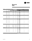
as follows:
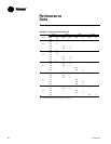
System Component Exhaust Pressurization
Heat/Cool off off
IGV closed open
Supply Fan off on
Exhaust Fan on off
Outside Air Damper closed open
Return Air Damper open closed
VAV Boxes n/a open