


RT-PRC007-EN14
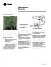
Model
Number
Description
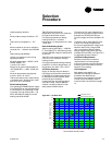
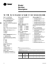
YCD480 A4 H A1 A4 F D1A0000000 00 000
5
12 3 456 7 8 9 1011 1213 14 151617 18192021222324 2526 272829
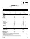
KW
Tons Voltage 36 54 72 90 108
27½ to 35 240 x x
480 xxxx
600 x x x
40 and 50 240 x
480 x x x x
600 x x x x
Digit 1, 2 — Unit Function
TC = DX Cooling, No Heat
TE = DX Cooling, Electric Heat
YC = DX Cooling, Natural Gas Heat
Digit 3 — Unit Airflow Design
D = Downflow Configuration
H = Horizontal Configuration
Digit 4, 5, 6 — Nominal Cooling Capacity
330 = 27½ Tons
360 = 30 Tons
420 = 35 Tons
480 = 40 Tons
600 = 50 Tons
Digit 7 — Major Development Sequence
A = First
Digit 8 — Power Supply (See Note 1)
E = 208/60/3
F = 230/60/3
4 = 460/60/3
5 = 575/60/3
Digit 9 — Heating Capacity (See Note 4)
0 = No Heat (TC only)
L = Low Heat (YC only)
H = High Heat (YC only)
Note: When second digit is “E” for Electric
Heat, the following values apply in the ninth
digit.
A = 36 KW
B = 54 KW
C = 72 KW
D = 90 KW
E = 108 KW
Digit 10 Design Sequence
A = First
Digit 11 — Exhaust
0 = None
1 = Barometric Relief
(Available w/Economizer only)
2 = Power Exhaust Fan
(Available w/Economizer only)
Digit 12 — Filter
A = Standard 2” Throwaway Filters
B = High Efficiency 2” Throwaway Filters
C = High Efficiency 4” Throwaway Filters
Digit 13 — Supply Fan Motor, HP
1 = 7.5 Hp Std. Eff.
2 = 10 Hp Std. Eff.
3 = 15 Hp Std. Eff.
4 = 20 Hp Std. Eff.
5 = 7.5 Hp Hi. Eff.
6 = 10 Hp Hi. Eff.
7 = 15 Hp Hi. Eff.
8 = 20 Hp Hi. Eff.
Digit 14 — Supply Air Fan Drive
Selections (See Note 3)
A = 550 RPM H = 500 RPM
B = 600 RPM J = 525 RPM
C = 650 RPM K = 575 RPM
D = 700 RPM L = 625 RPM
E = 750 RPM M = 675 RPM
F = 790 RPM N = 725 RPM
G = 800 RPM
Digit 15 — Fresh Air Selection
A = No Fresh Air
B = 0-25% Manual Damper
C = 0-100% Economizer, Dry Bulb Control
D = 0-100% Economizer, Reference
Enthalpy Control
E = 0-100% Economizer, Differential
Enthalpy Control
F = “C” Option and Low Leak Fresh
Air Damper
G = “D” Option and Low Leak Fresh
Air Damper
H = “E” Option and Low Leak Fresh
Air Damper
Digit 16 — System Control
1 = Constant Volume
2 = VAV Supply Air Temperature Control
w/o Inlet Guide Vanes
3 = VAV Supply Air Temperature Control
w/Inlet Guide Vanes
4 = VAV Supply Air Temperature Control
w/Variable Frequency Drive w/o Bypass
5 = VAV Supply Air Temperature Control
w/Variable Frequency Drive and Bypass
Note: Zone sensors are not included with
option and must be ordered as a separate
accessory.
Digit 17 - 29 — Miscellaneous
A = Service Valves (See Note 2)
B = Through the Base Electrical Provision
C = Non-Fused Disconnect Switch with
External Handle
D = Factory-Powered 15A GFI
Convenience Outlet and Non-Fused
Disconnect Switch with
External Handle
E = Field-Powered 15A GFI
Convenience Outlet
F = ICS Control Option — Trane
Communication Interface, Supply Air
Sensing and Clogged Filter Switch
G = Ventilation Override
H = Hinged Service Access
J = Condenser Coil Guards
K = LonTalk Communication Interface
L = Special
M = Stainless Steel Drain Pans
N = Black Epoxy Coated Condenser Coil
5. The service digit for each model number contains 29 digits; all 29 digits must be referenced.
Note:
1. All voltages are across the line starting only.
2. Option includes Liquid, Discharge, Suction Valves.
3. Supply air fan drives A thru G are used with 27½-35 ton units only and drives H thru N are used with 40 & 50
ton units only.
4. Electric Heat KW ratings are based upon voltage ratings of 240/480/600 V. Voltage offerings are as follows (see
table PD-9 for additional information):