


18
Application
Considerations
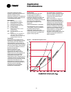
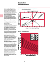
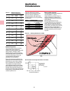
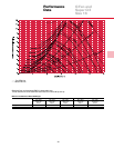
Parallel Fan Operation
The Q fan performance curve has a
characteristic shape where two
different cfm’s are possible at the same
static pressure. Therefore, when
selecting fans for multiple installation
connected with either a common inlet,
a common discharge or both, care
must be taken to eliminate the
possibility of fan paralleling.
Figure A-7 shows two typical cfm-sp
performance curves for the Q fan. Fan
paralleling can occur when multiple
fans are selected in the shaded area.
The shaded area is determined by
going straight across from the lowest
point of the fan performance curve at
the left of the surge line (A and A
1
) to
the same curve to the right of the surge
line (B and B
1
). Points B and B
1
fall on a
constant system curve.
Table A-3 — Maximum Torque For
Operation Of Inlet Vanes
Control Opening Closing
Arm Torque Torque
Size Class (In.) (In.-Lb) (In.-Lb)
1 8 7
16 2 8.75 14 13
3 23 22
1 12 11
19 2 8.75 21 19
3 34 31
1 17 15
21 2 8.75 31 26
3 32 44
1 26 20
24 2 8.75 48 36
3 79 61
1 37 27
27 2 8.75 66 48
3 109 79
1 52 35
30 2 8.75 94 63
3 155 104
1 65 41
33 2 8.75 128 81
3 212 134
1 100 59
36 2 10.81 180 106
3 298 175
1 138 75
40 2 10.81 249 136
3 412 225
1 193 99
44 2 10.81 349 179
3 576 295
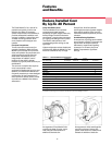
Motor and Drive Selection
The Model Q fan has been designed for
use with NEMA “T” Frame
motors. Motor hp limits for Class I, II,
and III construction are listed in the
roughing-in Dimensional Data section
of this catalog.
Minimizing belt tension forces
increases bearing life and reduces fan
noise. The Q fan and Super Q II fan
drive selection is totally computerized
by the factory to achieve quiet, long life
operation. If Trane provides Q fan
drives, all fan motor information must
be made available to the Trane sales
engineer.
Table A-4 defines this constant
system curve as a percent of wide-
open cfm. If fans in parallel are
always operated to the right of this
constant system curve, fan paralleling
will not occur.
Table A-4 — Parallel Operation
Minimum % of WOCFM
For Two Model Q Fans
Fan Size In Parallel
16 80% WOCFM
19-21 81% WOCFM
24-30 83% WOCFM
33-44 73% WOCFM
49-60 85% WOCFM
Figure A-7 — Selecting Model Q Fans in Parallel
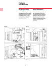
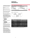
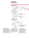
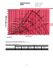
Recommended Q Fan Configuration Inside an Air Handler
Side View