


15
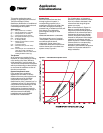
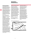
The following is the procedure to use
when selecting a fan for elevations and
temperatures other than standard:
1
Determine the air density from
Figure A-3.
2
Divide static pressure at the non-
standard condition by the air density
ratio.
3
Use the actual cfm and corrected static
pressure to determine rpm and bhp
from the fan performance tables.
4
The rpm is correct as selected.
5
The bhp must be multiplied by the air
density ratio determined in step one to
get the actual operating bhp.
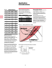
Option and Installation Kt Corrections
System effect losses due to less than
ideal inlet or outlet configuration can be
expressed in terms of velocity pressure
by the following expression:
Inlet SP Loss =
Kti
(
Inlet Velocity
)
2
4005
Where Kti =
Inlet Option Kt + Inlet Installation Kt
Outlet SP Loss =
Kto
(
Outlet Velocity
)
2
4005
Where Kto = Outlet Option Kt + Outlet
Installation Kt
Kt is the loss factor for the inlet or
discharge condition being considered.
It is necessary to add all of the static
pressure loss determined from the
above equation to the component
static pressure to determine the point
of duty static pressure for selection of
the fan.
Fan Option Kt Corrections
The fan static pressure should be
adjusted for fan options. Option
pressure drops are documented as Kt
losses and are handled the same way
as installation Kt effects (losses). Use
Table A-1, Q Fan/Super Q II Fan Kt
corrections, to determine the Kt values.
Add these values to any installation Kt
values. Use the result to select the fan.
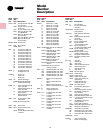
Table A-2 — Q Fan/Super Q II Fan Option Kt Corrections
Super Q II Pressure
Options Use Q-Fan Fan Drop (Kt)
Inlet Flange Connects to bolted inlet duct X 0
Inlet Bellmouth* Reduces Unducted Inlet Kt X X -.1
Inlet Plus Silencer Reduces inlet noise X X +.1
Inlet Screen Protects Unducted Inlets X X +.1
Outlet Screen Protects Unducted Outlets X +.5
Outlet Flange Connects to bolted outlet duct X 0
Outlet Equalizer (Diffuser) Improves SE X 0
Outlet Plus Silencer Reduces Outlet Noise X X +.1
Outlet Flow Stabilization Screen Reduces Outlet swirl X X +.8
Outlet Backdraft Damper Isolates fan from duct Special Special +.5
Frequency Drive Modulation Modulates Q Fan quietly Special Special 0
Belt Guard Protects drives/belts X 0
Motor Rails Allows motor to be mounted X Included 0
Standard Isolators Isolates fan X Included 0
Seismic Isolators Isolates fan X Special 0
*Note: Bellmouth effect included in unducted installation Kt correction. Fan sizes 49 through 60 fan curves are cataloged
with inlet bells. For unducted inlets without bells on size 49 through 60 fans add .1 to the inlet Kt given above.
Inlet vane losses are covered in the Selection Procedure with air density corrections (page 20).
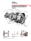
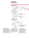
Application
Considerations
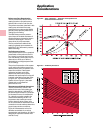
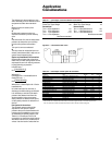
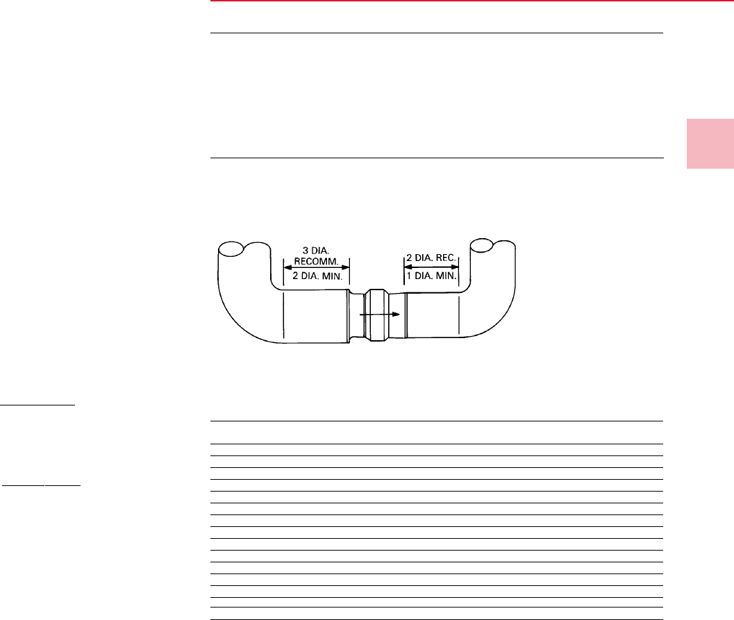
Table A-1 — Q Fan/Super Q II Fan Installation Kt Corrections
Unducted (Plenum) Inlet*
Draw-Thru Type Design 0.0
Ducted Inlet
Turn > 3 Dia Upstream -1.0
Turn 2 Dia Upstream +.8
Turn 1 Dia Upstream +1.3
Turn < 1 Dia Upstream
Not Recommended
Unducted Outlet
Blow-Thru Type Design +.8
Ducted Outlet
Turn > 2 Dia Downstream 0.0
Turn 1 Dia Downstream +1.3
Turn < 1 Dia Downstream
Not Recommended
Figure A-4 — Ducted Turns Near Q Fan