


Wireless remote controller kit
Installation Manual
–8–
EN
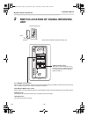
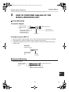
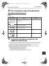
5 HOW TO PERFORM CABLING OF THE
SIGNAL RECEIVING UNIT
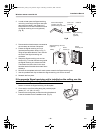
Flush Mounting
Connection diagram
Provided wire joint (WHT 2)
1. Strip the insulation to approximately 0.55” (14 mm) from the ends of the wires to be connected.
2. Twist together the 2 wires and create a crimp connection at the wire joint.
3. If a special crimping tool is not used, or if the connection is soldered, insulate the wires using
insulation tape.
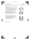
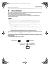
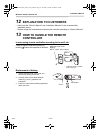
Exposed Mounting
• Connection diagram
Signal receiving unit
Power wire from
Signal receiving unit
Connector
Wire of Signal receiving
unit (Field procurement)
(AWG20 (0.5 mm
2
))
(UL wires rated 300 V)
Indoor unit remote
controller terminal
board
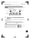
Wire of Signal
receiving unit
(Field procurement)
Wire joint
(provided)
Power wire from
Signal receiving
unit
Indoor unit remote
controller terminal
board
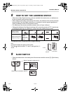
Signal receiving unit
Remote controller cord (optional)
8-EN
+00EH99677601_01EN_remo_IM.book Page 8 Thursday, October 8, 2009 4:12 PM