


Wireless remote controller kit
Installation Manual
–6–
EN
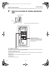
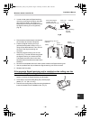
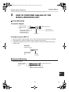
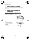
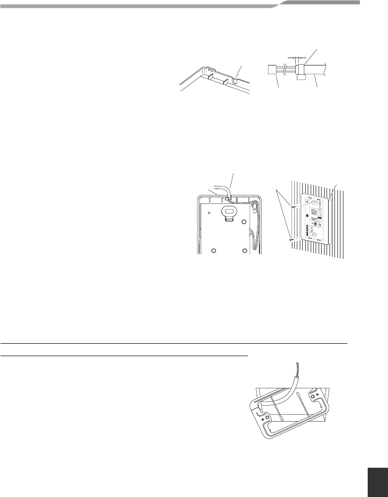
2. In order to later pass the Signal receiving
unit wiring out through the upper case (thin
part at the top center), use nippers or a
similar tool to cut a notch in the same size as
the Signal receiving unit cord (optional).
(Fig. B)
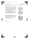
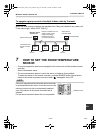
3. Disconnect the wires that were connected to
the connector at the time of shipment.
4. Fasten the Signal receiving unit cord
(optional) at the position shown in Fig. C,
using the provided cable tie. Then connect
the cord to the Signal receiving unit
connector.
5. Shape the Signal receiving unit cord as
shown in Fig. C so that it fits at the top inside
the Signal receiving unit, above the PCB.
Then attach the lower case. At this time,
bend the head of the cable tie so that it faces
sideways.
6. Remove the nameplate and use 2 wood screws to attach the Signal receiving unit.
7. Use the provided cord clips to fasten the Signal receiving unit cord to the wall.
8. Reattach the face plate.
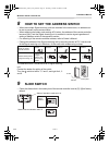
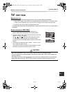
If the separate Signal receiving unit is installed on the ceiling, use the
provided ceiling mounting bracket for installation.
1. Insert a screwdriver or similar tool into the notch at the
bottom to remove the Signal receiving unit face plate.
2. Cut a section out of the ceiling along the provided paper
pattern (3.7” x 2” (95 x 51 mm)).
3. Pass the wire through the provided mounting bracket and
insert the bracket into the installation hole. (Fig. D)
Cable tie
0.08”-0.12”
(2–3 mm)
Signal receiving
unit cord
(optional)
Fig.B
Notch where Signal
receiving unit cord
passes through top case
Connector
1
3
2
4
6
5
Signal
receiving unit
Wood
screws (2)
Fig.C
Signal receiving unit cord
(optional)
Clamp
Fig.D
6-EN
+00EH99677601_01EN_remo_IM.book Page 6 Thursday, October 8, 2009 4:12 PM