


–8–
Under Ceiling Type
Installation Manual
EN
Toshiba
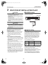
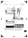
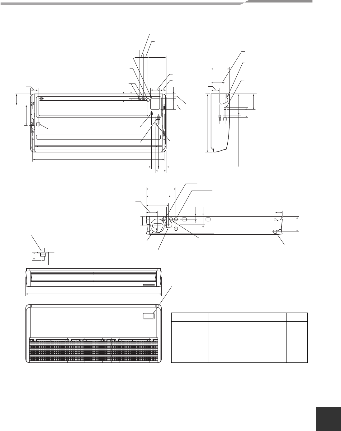
Unit: in (mm)
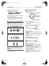
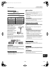
Considering pipe/wire connecting work inside the ceiling after the indoor unit has been hanged, select an
installation place and determine piping direction.
• If the ceiling has already been set before hanging the main unit, prepare refrigerant pipe, drain pipe, indoor
connecting wire, remote control cord, etc. up to the place where pipe and wire can be connected.
• Check the size of the indoor unit, and match the indoor unit size using the attached installation pattern.
A
Unit: in (mm)
Model name A B C D
180CT
35.8”
(910)
33.7”
(855)
Ø1/4”
(6.4)
Ø1/2”
(12.7)
240CT
46.5”
(1180)
44.3”
(1125)
Ø3/8”
(9.5)
Ø5/8”
(15.9)
300CT, 360CT
to 420CT
62.8”
(1595)
60.6”
(1540)
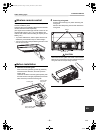
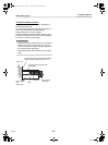
Conduit hole
(Hole for power supply cable. knockout)
Hole for remote control wires (knockout)
Left drain size
Refrigerant pipe
(Liquid side ØC)
B (Hanging position)
Refrigerant pipe (Gas side ØD)
Upper pipe draw-out port (knockout)
Pipe draw-out port
(knockout)
Drain port VP20
(Inner dia. Ø1.0” (26), hose
attached)
8.5” (216) (Gas pipe)
7.9” (200) (Liquid pipe)
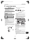
Drain pipe
connecting
port
Hole for remote control wires
Conduit hole
(knockout)
Left drain pipe
draw-out port
(knockout)
Hole for power supply cable
Outside air take-in port (Duct sold separately)
Knockout hole Ø3.6” (92))
Pipe hole on wall
(Ø3.9” (100) hole)
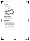
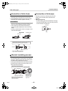
Unit
Ceiling surface
Hanging bolt
Within
2.0” (50)
Wireless sensor
mounting section
3.3” (84)
8.5” (216)
4.3” (110)
3.0” (76)
4.1” (105)
8.3” (210)
6.6” (167)
3.8” (97)
3.0” (75)
5.7” (146)
13.7” (347)
12.2” (311)
5.3” (135)
3.3” (84)
12.6” (320)
6.7” (170)
5.7” (145)
3.5”
(90)
1.3” (32)
3.6” (92)
6.7” (171)
2.1”
(53)
5.1” (130)
2.0” (50)
26.8” (680)
5.6” (141)
4.5” (114)
10.3” (262)
1.5” (39)
2.0” (52)
2.8”
(70)
8-EN
+00EH99864801_00Ta.book Page 8 Tuesday, November 24, 2009 5:40 PM