–16–
Under Ceiling Type
Installation Manual
EN
Toshiba
6 ELECTRICAL CONNECTION
WARNING
1. Using the specified wires, ensure to connect the
wires, and fix wires securely so that the external
tension to the wires do not affect the connecting
part of the terminals.
Incomplete connection or fixation may cause a fire,
etc.
2. Be sure to connect ground wire. (grounding work)
Incomplete grounding cause an electric shock.
Do not connect ground wires to gas pipes, water
pipes, lightning rods or ground wires for telephone
wires.
3. Appliance shall be installed in accordance with
national wiring regulations.
Capacity shortage of circuit breaker or incomplete
installation may cause an electric shock or a fire.
CAUTION
• Consult local building codes, NEC (National Electrical
Code) or CEC (Canadian Electrical Code) for special
requirements.
• This indoor unit has no power cord.
• If incorrect/incomplete wiring is carried out, it will
cause an electrical fire or smoke.
• Be sure to install circuit breaker is not tripped by shock
waves.
If circuit breaker is not installed, an electric shock may
be caused.
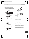
• Be sure to use the cord clamps attached to the
product.
• Do not damage or scratch the conductive core and
inner insulator of power and system interconnection
wires when peeling them.
• Use the power cord and system interconnection wire
of specified thickness, type, and protective devices
required.
REQUIREMENT
• For power supply wiring, strictly conform to the
Local Regulation in each country.
• For wiring of power supply of the outdoor units,
follow the Installation Manual of each outdoor unit.
• Never connect 208/230 V power to the terminal
blocks (A, B etc.) for control wiring.
(Otherwise, the system will fail.)
• Perform the electric wiring so that it does not come
to contact with the high-temperature part of the
pipe.
The coating may melt resulting in an accident.
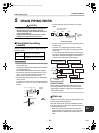
• Run the refrigerant piping line and control wiring line
in the same line.
• Do not turn on the circuit breaker of the indoor unit
until vacuuming of the refrigerant pipes completes.
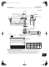
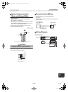
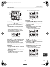
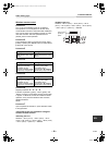
Remote control wiring
• For single system, use 2 x AWG20 non polarity wire
is used for the remote control wiring.
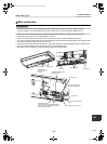
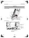
Wiring
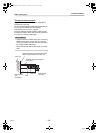
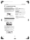
1. Connect the connecting wire to the terminal as
identified with their respective numbers on the
terminal block of indoor and outdoor unit.
(4
x AWG12)
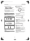
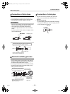
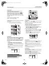
2. Insulate the unsheathed redundant cords
(conductors) with electrical insulation tape.
Process them so that they do not touch any electrical
or metal parts.
3. For inter-unit wiring, do not use a wire jointed to
another on the way.
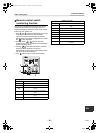
*
1
:Length of the system interconnection wires.
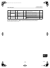
Wire Quantity x size
Indoor unit - Outdoor unit *
1
3 x AWG12 (polar)
Ground 1 x AWG12 or thicker
Remote control 2 x AWG20 (non-polar)
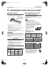
RAV- SP180AT2 SP240AT2
SP300AT2 -
SP420AT2
Wire
length
164’1” (50
m) or less
229’8” (70
m) or less
246’1” (75 m) or
less
16-EN
+00EH99864801_00Ta.book Page 16 Tuesday, November 24, 2009 5:40 PM