–11–
Under Ceiling Type
Installation Manual
Toshiba
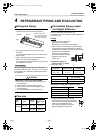
4 REFRIGERANT PIPING AND EVACUATING
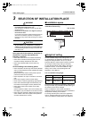
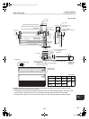
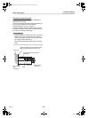
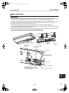
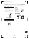
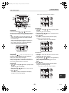
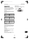
Refrigerant Piping
• The connecting sections of the refrigerant pipes are
provided at the positions in the figure below.
1. Use copper pipe with 0.03” (0.8 mm) or more
thickness.
(In case pipe size is Ø5/8” (15.9 mm), with 0.04” (1.0
mm) or more.)
2. Flare nut and flare works are also different from
those of the conventional refrigerant.
Take out the flare nut attached to the main unit of the
air conditioner, and use it.
REQUIREMENT
When the refrigerant pipe is long, provide support
brackets at intervals of 8’2” - 9’10” (2.5 - 3 m) to clamp
the refrigerant pipe. Otherwise, abnormal sound may
be generated.
CAUTION
IMPORTANT 4 POINTS FOR PIPING WORK
1. Remove dust and moisture from the inside of the
connecting pipes.
2. Tight connection (between pipes and unit)
3. Evacuate the air in the connecting pipes using
VACUUM PUMP.
4. Check the gas leakage. (Connected points)
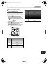
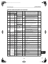
Pipe size
Permissible Piping Length
and Height Difference
They vary according to the outdoor unit.
For details, refer to the Installation Manual attached to
the outdoor unit.
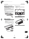
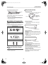
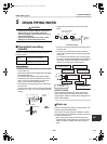
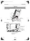
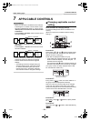
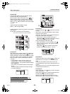
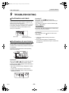
Flaring
• Cut the pipe with a pipe cutter.
Remove burrs completely.
Remaining burrs may cause gas leakage.
• Insert a flare nut into the pipe, and flare the pipe.
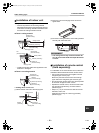
As the flaring sizes of R410A differ from those of
refrigerant R22, the flare tools newly manufactured
for R410A are recommended.
However, the conventional
tools can be used by adjusting
projection margin of the
copper pipe.
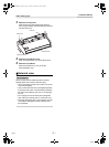
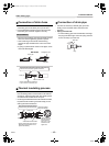
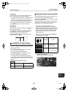
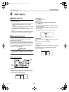
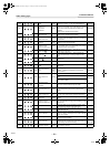
▼ Projection margin in
flaring: B (Unit: in (mm))
Rigid (Clutch type)
▼ Flaring dia. meter size: A (Unit: in (mm))
* In case of flaring for R410A with the
conventional flare tool, pull it out approx.
0.02” (0.5 mm) more than that for R22 to
adjust to the specified flare size.
The copper pipe gauge is useful for
adjusting projection margin size.
Model
name
RAV-
SP180
type
SP240, SP300,
SP360, SP420
type
Pipe size
Gas side
1/2"
(12.7 mm)
5/8"
(15.9 mm)
Liquid side
1/4"
(6.4 mm)
3/8"
(9.5 mm)
Rear side
* When using the drain
pump kit sold separately,
the pipe can be drawn out
only from the upper side.
Upper side
Right
Outer dia. of
copper pipe
R410A tool used
Conventional
tool used
1/4” - 5/8”
(6.4 - 15.9)
0 - 0.02”
(0 - 0.5)
0.04” - 0.06”
(1.0 - 1.5)
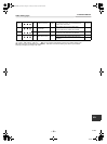
Outer dia. of copper pipe
Imperial
(Wing nut type)
1/4” (6.4) or 3/8” (9.5) 0.06” - 0.08” (1.5 - 2.0)
1/2” (12.7) or 5/8” (15.9) 0.08” - 0.1” (2.0 - 2.5)
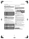
Outer dia. of copper pipe A
1/4” (6.4) 0.36” (9.1)
3/8” (9.5) 0.52” (13.2)
1/2” (12.7) 0.65” (16.6)
5/8” (15.9) 0.78” (19.7)
B
+0
-0,02" (–0.4)
A
11-EN
+00EH99864801_00Ta.book Page 11 Tuesday, November 24, 2009 5:40 PM