


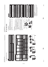
– 114 –
EN-26 26
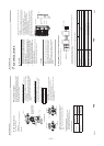
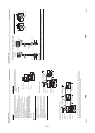
Super Digital Inverter
14
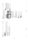
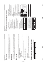
TROUBLESHOOTING
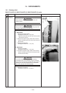
You can perform fault diagnosis of the outdoor unit with the LEDs on the P.C. board of the outdoor unit in addition to using the
check codes displayed on the wired remote controller of the indoor unit.
Use the LEDs and check codes for various checks. Details of the check codes displayed on the wired remote controller of the
indoor unit are described in the Installation Manual of the indoor unit.
Verifying current abnormal status
1. Check that DIP switch SW803 is set to OFF.
2. Jot down the states of LED800 to LED804. (Display mode 1)
3. Press SW800 for at least 1 second. The LED status changes to display mode 2.
4. Check the code whose display mode 1 equals the LED states jotted down and display mode 2 equals the current flashing
status of LED800 to LED804 from the following table to identify the cause.
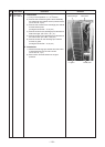
Verifying an abnormal state in the past although the abnormal state no longer occurs
1. Set bit 1 of DIP switch SW803 to ON.
2. Jot down the states of LED800 to LED804. (Display mode 1)
3. Press SW800 for at least 1 second. The LED status changes to display mode 2.
4. Find an error whose display mode 1 equals the LED states jotted down and display mode 2 equals the current flashing
states of LED800 to LED804 from the following table to identify the error.
• An outside air temperature (TO) sensor error can be checked only while it occurs.
27 27-E
N
Super Digital Inverter
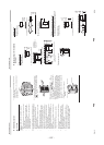
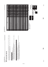
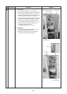
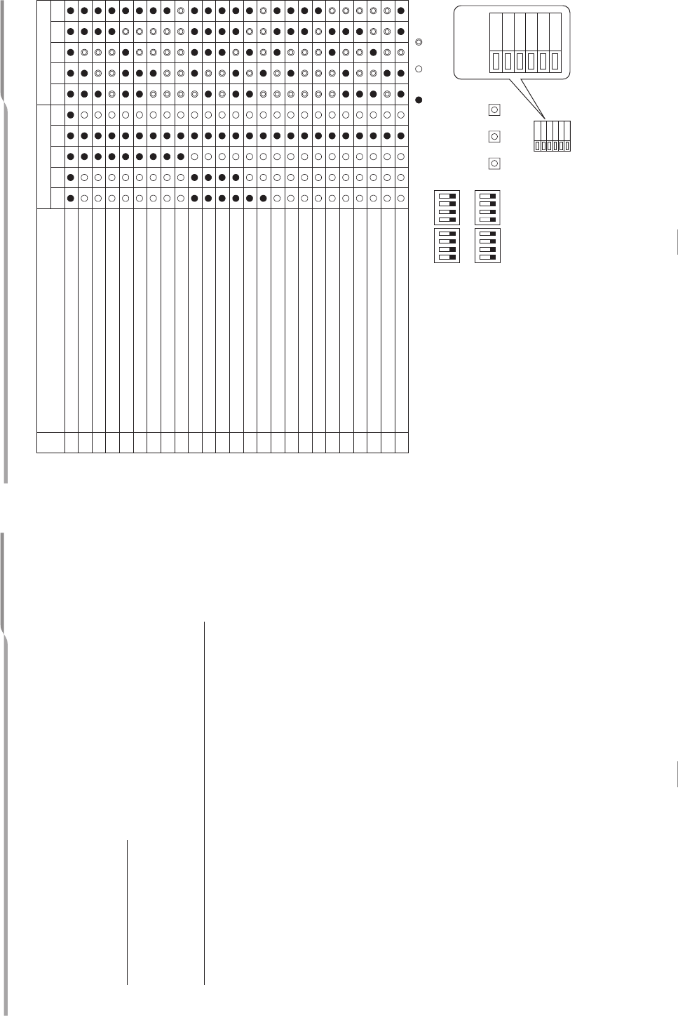
( : OFF : ON : Flashing)
* The LEDs and DIP switches are
located on the lower left of the P.C.
board of the outdoor unit.
No. Cause
Display mode 1 Display mode 2
D800 D801 D802 D803 D804 D800 D801 D802 D803 D804
1Normal
2 Discharge (TD) sensor error
3 Heat exchanger (TE) sensor error
4 Heat exchanger (TL) sensor error
5 Outside air temperature (TO) sensor error
6
Suction (TS) sensor error
7 Heat sink (TH) sensor error
8 Outdoor temperature sensor (TE/TS) connection error
9 Outdoor EEPROM error
10 Compressor breakdown
11 Compressor lock
12 Current detection circuit error
13 Thermostat for compressor activated
14 Model data not set (on the service P.C. board)
15 MCU-MCU communication error
16 Discharge temperature error
17 Abnormal power (open phase detected or abnormal voltage)
18 Heat sink overheat
19 Gas leak detected
20 4-way valve reverse error
21 High pressure release operation
22 Outdoor fan motor error
23 Compressor driver short-circuit protection
24 Position detection circuit error in one-line display
25 High pressure SW error
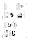
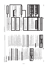
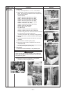
SW800 SW801 SW806SW802 SW803
LED
ON
1234
ON
1234
SW804 SW805
ON
1234
ON
1234
D805
D804
D803
D802
D801
D800
D805
D804
D803
D802
D801
D800
Enlarged view of
LEDs