– 76 –
9. CIRCUIT CONFIGURATION AND CONTROL SPECIFICATIONS
9-1. Outdoor Controls
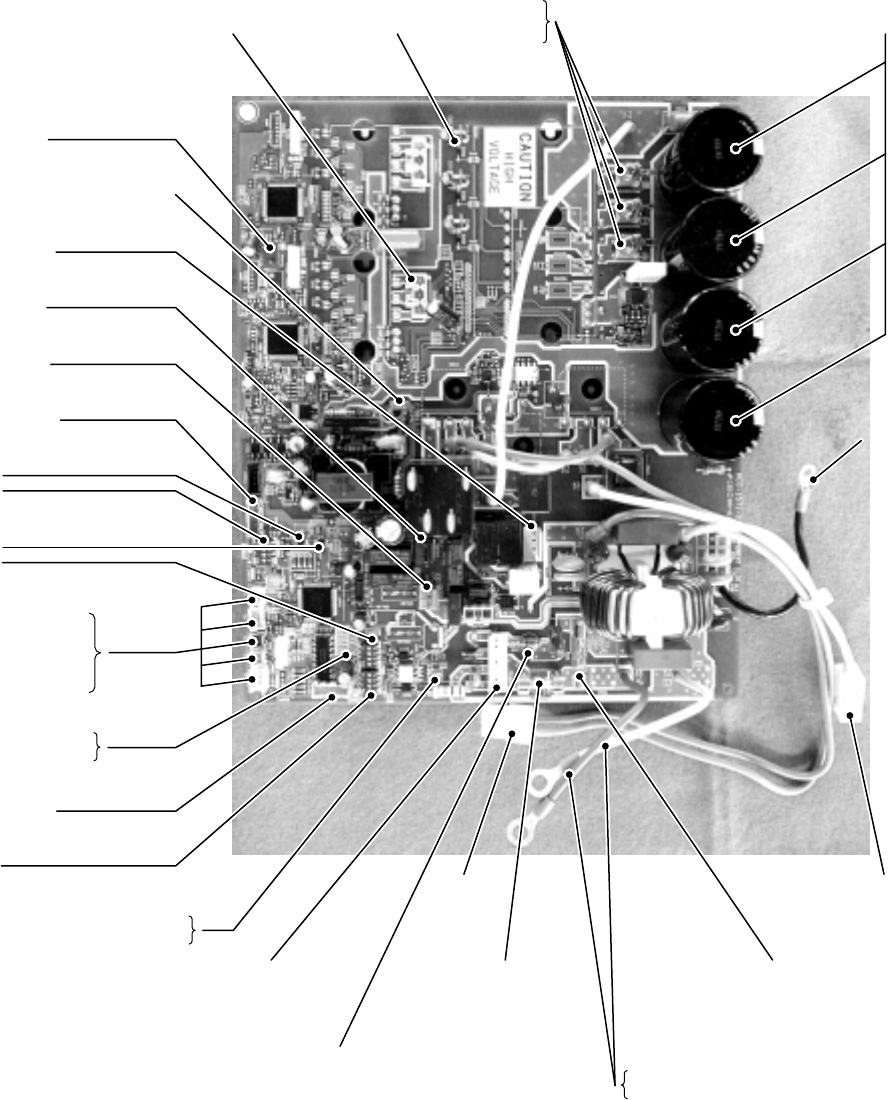
9-1-1. Print Circuit Board
<Viewed from parts of P.C board>
RAV-SP1104AT-E, RAV-SP1404AT-E
RAV-SP1104ATZ-E, RAV-SP1404ATZ-E
RAV-SP1104ATZG-E, RAV-SP1404ATZG-E
<MCC-1571>
Case thermostat connector
CN609 (Blue)
Power supply circuit protective fuse
F100 250V, 3.15A, Plastic case)
4-way valve connector
CN701 (White)
Compressor ON output connector
CN704 (Blue)
Heater output connector
CN610 (Gray)
Outside input connector
CN610 (Yellow)
Specific operation switch
SW801
SW804
Display select switch
SW800
SW803
Power-ON, error display LED
D800 to 804 (Yellow)
D805 (Green)
PMV connector
CN710 (White)
Initial setting switch
SW802
Indoor/Outdoor communication signal LED
D503 (Green, Outdoor → Indoor)
D502 (Orange, Indoor → Outdoor)
Temp. sensor connector
TL CN604 (White)
TD CN603 (White)
TO CN602 (Yellow)
TE CN601 (White)
TS CN600 (White)
Fan motor output
(Lower side)
CN300 (White)
Fan motor output
(Upper side)
CN400 (White)
Compressor output terminal
CN202
CN201
CN200
Electrolytic
condenser
4-way valve protective fuse
F700 (250V, 3.15A, Plastic case)
Power supply
protective fuse
F01 (250V, 25A)
Inter-unit cable
protective fuse
F03 (250V, 25A)
Inter-unit
cable connector
CN04 (White)
Lead wire for connection of power supply
P01 (Red)
P02 (White)
Connector
for reactor
Connector
for reactor
Connector
for reactor
Connector
for reactor
Lead wire
for grounding
P09 (Black)
Lead wire
for grounding
P09 (Black)


