


– 36 –
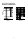
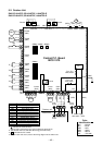
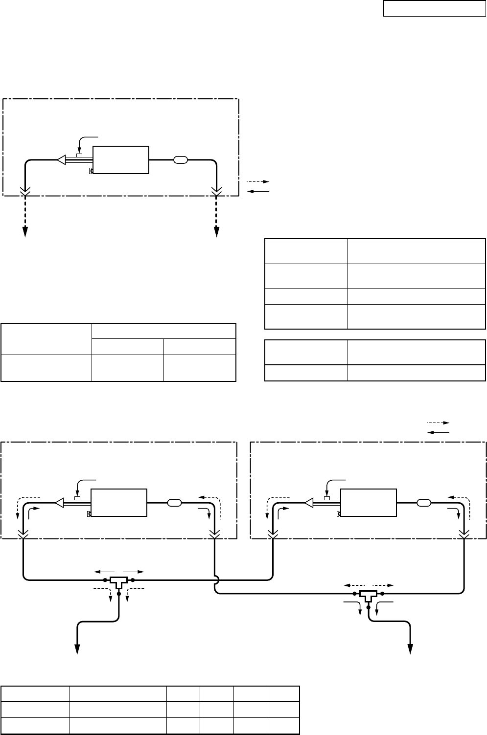
(Indoor unit A)
Refrigerant pipe
at liquid side
(Outer dia : ØA)
Refrigerant pipe
at liquid side
(Outer dia : ØC)
Refrigerant pipe
at gas side
(Outer dia : ØB)
Distributor
(Strainer incorporated)
Strainer
TCJ sensor
TC sensor
Air heat
exchanger
To outdoor unit
Branch pipe
(Indoor unit B)
Refrigerant pipe
at liquid side
(Outer dia : ØA)
Refrigerant pipe
at liquid side
(Outer dia : ØD)
Refrigerant pipe
at gas side
(Outer dia : ØB)
Distributor
(Strainer incorporated)
Strainer
TCJ sensor
TC sensor
To outdoor unit
Branch pipe
Air heat
exchanger
Heating
Cooling
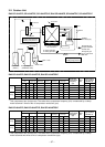
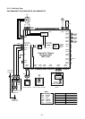
(Indoor unit)
Refrigerant pipe
at liquid side
(Outer dia : ØB)
Refrigerant pipe
at gas side
(Outer dia : ØA)
Distributor
(Strainer incorporated)
Strainer
Heating
Cooling
TCJ sensor
TC sensor
Air heat
exchanger
To outdoor unit
To outdoor unit
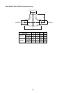
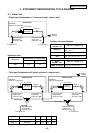
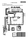
3. SYSTEMATIC REFRIGERATING CYCLE DIAGRAM
3-1. Indoor Unit
• Single type (Combination of 1 indoor unit and 1 outdoor unit)
• Twin type (Combination of 2 indoor units and 1 outdoor unit)
Indoor unit
SM56 × 2
SM80 × 2
Branch pipe RBC-
TWP30E2
TWP50E2
ABCD
6.4 12.7 9.5 15.9
9.5 15.9 9.5 15.9
Dimension table
Indoor unit
SM80, 110, 140, 160
type
Outer diameter of refrigerant pipe
Gas side ØA Liquid side ØB
15.9 9.5
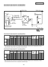
Capillary tube specifications
Model
RAV-SM∗∗∗UT
SM56 type
SM80 type
SM110, 140 , 160
type
Inner dia. × Length × Q’ty
Ø2 × 250 × 2, Ø2 × 350 × 1
Ø2 × 700 × 1
Ø2 × 250 × 3, Ø2 × 500 × 1
Ø2 × 200 × 1, Ø2 × 300 × 2
Ø2 × 350 × 2, Ø2 × 700 × 1
Model
RAV-SM∗∗∗SDT
SM40, 45, 56 type
Inner dia. × Length × Q’ty
Ø2 × 200 × 2, Ø2 × 350 × 1
Revised 2: Jun., 2008