


– 35 –
140
633
320
160
742
1093
60
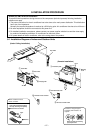
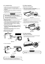
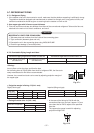
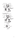
9-5-5. Console Installation
• Select the terminal of Selector-SW from [C position]
to [F position].
Fig. 9-5-18
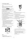
390 mm
or more
375 mm
or more
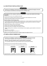
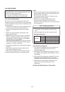
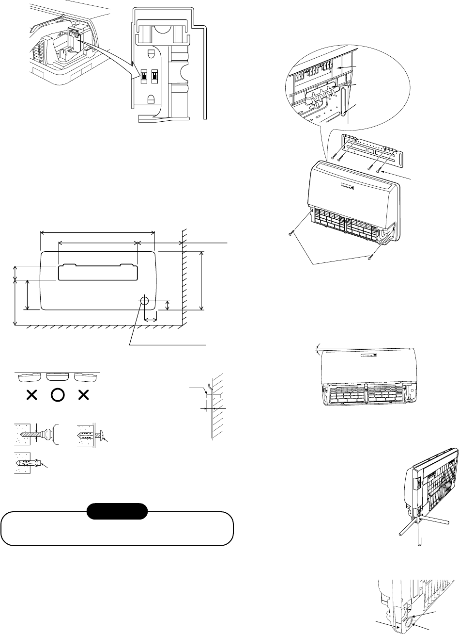
CAUTION
Failure to firmly install the unit may result in personal
injury and property damage if the unit falls.
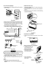
• In case of block, brick, concrete or similar type walls,
make 5 mm dia. holes in the wall.
• Insert clip anchors for appropriate Mounting screws
4.
NOTE :
• Secure four corners and lower parts of the
Installation plate 1 with 6 to 8 mounting screws to
install it.
<Condition for installation>
• The unit must not decline more than 15 mm in either
axis.
Fig. 9-5-22
Projection
15 mm or less
44
44
4 Mounting screw
∅4 x 25
ss
ss
s
Clip anchor
(local parts)
5 mm dia. hole
Anchor bolt
15 mm
Indoor unit
Hook
11
11
1 Installation
plate
44
44
4 Mounting screw
44
44
4 Mounting screw
<Install the indoor unit>
• Install the Installation plate 1 at the wall according
to the Paper pattern.
• Hang the indoor unit on the hooks of the Installation
plate 1.
• Fix the lower portion of the indoor unit with Mounting
screws 4 (2 places).
Fig. 9-5-21
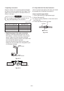
<Cutting a hole and mounting the Installation plate>
• When installing the rear piping, determine the pipe
hole position, drill the pipe hole (∅80 mm) at a slight
downward slant to the outdoor side.
• For mounting of the Installation plate 1, use the
Paper pattern, which is inside the package box cover.
Fig. 9-5-19
Fig. 9-5-20
Rear piping hole ∅80
Floor
REMOCON
INSTALL
A
C
B
F
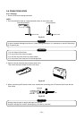
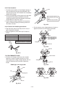
<Piping and Drain Hose Installation>
• The piping direction can
be the following 3 ways
with the Drain hose.
• Each piping direction
should be connected with
the Flexible pipe 5.
• Cut or remove the
determined direction
slit or cover.
Slit for upper
piping
Cover for
side piping
Side piping
Rear piping
Bottom piping
Cover for rear
upper piping
Fig. 9-5-22
Fig. 9-5-23