


– 88 –
Concealed Duct High Static Pressure
Installation Manual
Concealed Duct High Static Pressure
Installation Manual
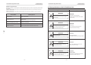
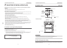
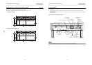
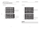
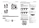
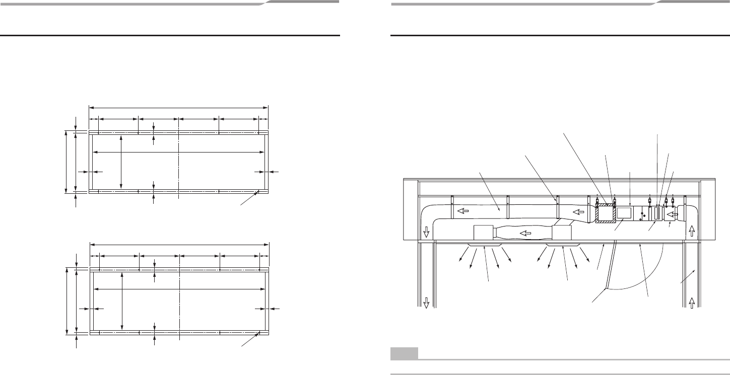
n Diagrams for making connecting flanges (Unit: mm)
The connecting flange (Incl. the fixing screw) is not supplied to the indoor unit.
When the connecting flange is necessary, produce them in locally.
Drawing figure is as follows. (Material: Galvanized steel plate, thickness of 1.6 mm)
<Air outlet port flange>
1130
1080
394
370
344
12 12
25
2525
25
65
250 250 65250250
10-Ø8 hole
1130
1080
430
406
380
12 12
25
2525
25
65
250 250 65250250
10-Ø8 hole
<Air inlet port connecting flange>
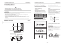
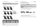
n Duct design
1. In order to prevent short circuits, design the duct installation, so that the intake and discharge openings are not adjacent
to each other.
2. The indoor unit does not have a built-in air filter. Make sure to set up the filter chamber etc. and install the air filter
(Locally procured).
If no air filter is installed, the heat exchanger will be blocked by dust, which may cause the malfunction of air conditioner
or the water leakage.
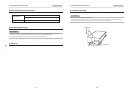
<Duct installation example (First floor)>
Duct hose (with heat insulation)
Flexible duct hanging band
Air outlet chamber
(with heat insulation)
High efficiency filter
inserting port
Air outlet port
connecting flange
Pre filter
inserting port
Indoor unit
Air inlet port
connecting flange
Air inlet
chamber
Filter
chamber
Electrical
control box
To ground floor From ground floor
Duct hose
Check port or carrying
in port (600 × 600)
Check port cap
Ceiling
Air outlet port Air outlet port
NOTE
All duct connection between units except outdoor unit must be procured and enforced locally.
– 13 – – 14 –