


– 17 –
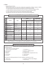
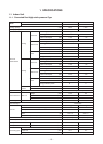
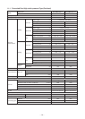
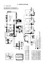
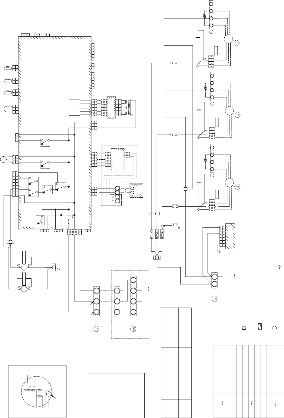
4. WIRING DIAGRAM
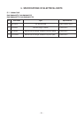
4-1. Indoor Unit
RAV-SM2242DT-E, RAV-SM2802DT-E
RAV-SM2242DT-TR, RAV-SM2802DT-TR
A
220-240V 50Hz
43F1,43F2
Fan Motor Control Relay
F1 3
Fuse for Fan Motor
DP
Drain Pump Motor
RY001
Louver Control Relay
RY002
Drain Control Relay
RY005 007
Fan Motor Control Relay
TC,TCJ
Temp sensor
TA
Indoor temp sensor
TR
Transformer
RC
Running Capacitor
FM1 3
Symbol
Fan Motor
Parts nam
e
9
CN051
(RED)
(BLU)
CN040
Adapte
r
21
1 2
TCC-LINK
5
5
432
1
3
421
54321
S(N)R(L)
COLOR
IDENTIFICATIO
N
RED:RED
WHI:WHITE
YEL:YELLOW
BLU:BLUE
BLK:BLACK
GRY:GRAY
PNK:PINK
ORN:ORANGE
GRN:GREEN
BRW:BROW
N
ORN
RED
WH
I
Outdoor Unit
Earth
Scre
w
Indoor Unit
Earth
Screw
Power Supply
380-415V 3N 50H
z
Indoor Unit
Earth
Scre
w
Indoor Fan
Power Supply
WHI
RED
RED WHI BL
K
231
BLK
55
MCC-1263
CN100
(WHI
)
73 5
3 75
1
1
321
NL3L2L1
WHIWHI
A B
spark killer
(Option)
(WHI)
CN01
CN02
(YEL
)
TCC-LINK Adapte
r
MCC-1520
Sub P.C.Boar
d
421 3 5 6
6531 2 4
42135
6
6531 2 4
TR
T10A,250V
T10A,250V
T10A,250V
TC
(Option)
TA
TC
J
6
31 2
21 3
4
4
4
2
456 121 532 4 6
2
1
2
2
12
2
1
2
1
3
1
CN032
(WHI)
FAN
DRIVE
OPTION
CN060(WHI)
CN070
(WHI)
CN073
(RED)
EXCT
CN080
(GRN)
PNL
CN101
(BLK)
4P
(WHI)
FAN1
43F1
Note
Setting from factory
FM1
321
3
21
3
5
3
5
6
4
4
5
1
32
1 23
4
4
4
A
B
7
33
1
2
1
1
1
3
8
7
8
7
3
3
4
41
1
3
3
2
32 41 5
3
3
1
1
2
21
1
3
3
397
7
5 1 3
3
1
1
3
1
21
1
5
56
6 1 2
12
2
1
Power
supply
circui
t
RED
RED
RED
WHI
FAN
CN083(WHI)
CN304(GRY)
RY004
CN309
(YEL)
RED ACIN
WHI
CN067(BLK)
CN066(WHI) CN041(BLU) CN050(WHI)
CN074(WHI)
(WHI)
CN075
CN104
(YEL)
CN030
(RED)
FS
LM
CN033
(GRN)
DP
CN068
(BLU)
RC
Remote
Controller
BLKBLK
RED
RED
RED
F1
F2
F3
RED
RED
RED
RED
ORN
WHI
RED
RED
GRY
GRY
WHI
(RED)
FAN3
4P
YEL
BLU
ORN
RC
WHI
RED
GRY
WHIREDGRY
4P
(BLU)
FAN2
RC
43F1
43F2
43F2
RY002
RY001
1. indicates the terminal block.
Letter at inside indicates the terminal number.
2.A dotted line and broken line indicate the wiring at site.
3. indicates the control P.C board.
4.When installing the drain pump connect
the froat switch connector to CN030 connector.
5. A position is connected to terminal block when change to static pressure.
exchange the lead wire of arrow( ) position after check the terminal
number as figure and lead wire's color of fan motor
.
Terminal
No.
Fan motor
wiring
F
1
2
F
3
F
YEL
BLU
ORN
Fan motor inside
wiring diagram
BLK
WHI
GRY
RED
YEL
ORN
BLU
Motor over heating
protection switch
49F
43F1
43F2
6
RY007
HM
LUL
RY006
RY005
FM3
FM2
F1 F2 F3 F4
Fuse
T5.0A 250V
3
1
1
Control P.C. Board
for Indoor Unit
CN061(YEL)
CN102
(RED)
Static pressure
Pa (mmAg)
69 (7)
137 (14)
196 (20)
MCC-140
3
DP
spark killer
YEL
BLU
ORN
F1 F2 F3 F4
ORN
RC
WHI
RED
GRY
WHI
REDGRY
YEL BLU
ORN
F1 F2 F3 F
4
U3U4
(Option)
FILTER
#187
FASTO
N
#250
FASTO
N
#250
FASTON
1
3