


– 142 –
No.
4
Part name
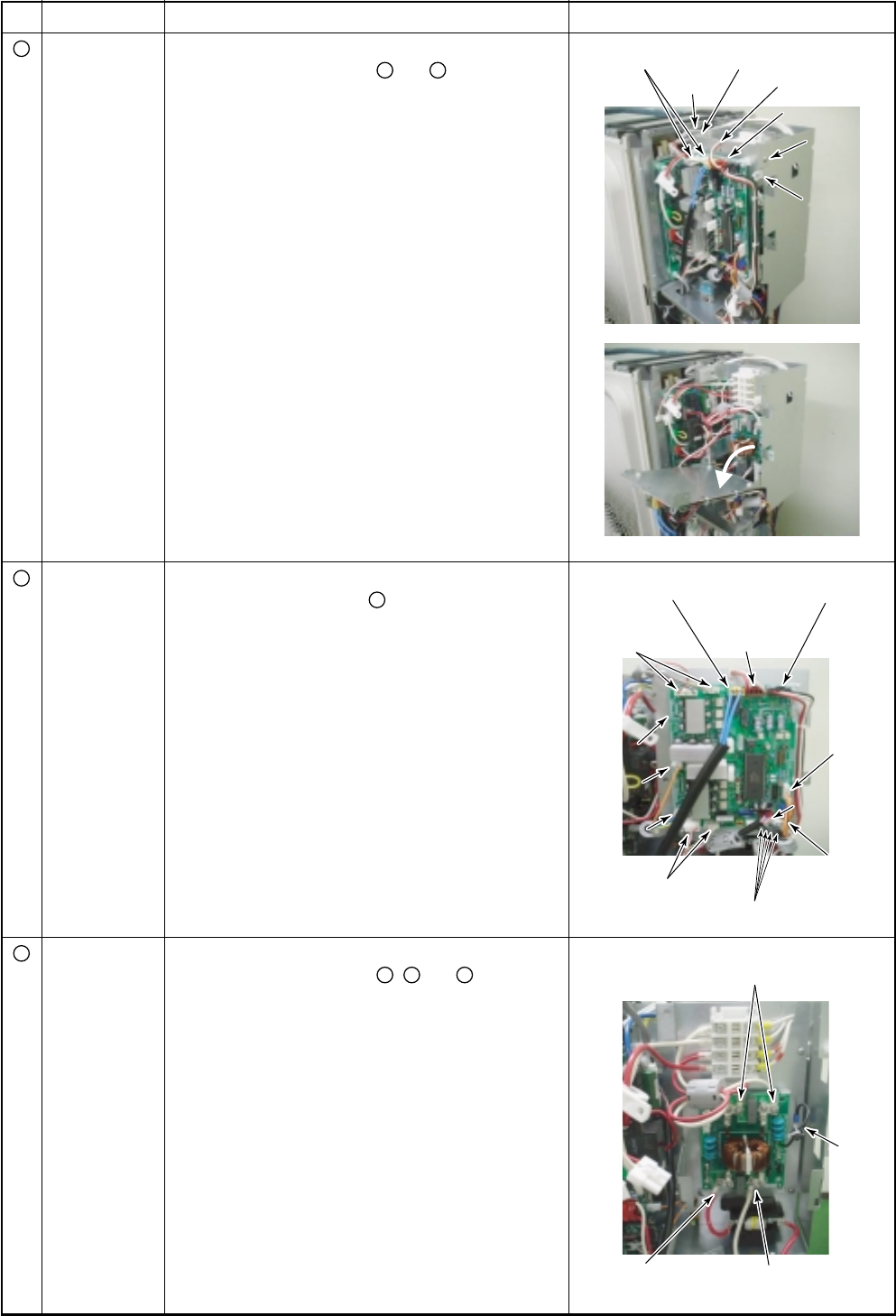
Replacement
of electric parts
Common
procedure
Procedure
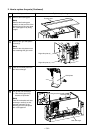
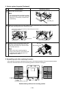
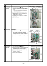
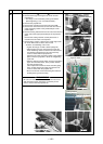
1. Detachment
1) Carry out works of 1 of
1
and
3
.
2) Remove the connectors connected to CDB board.
(Connector of power supply and upper side fan
motor)
• Unlock the lock of the housing part and then
remove the connectors.
3) Cut the bundling band which binds the power
supply leads.
4) Remove the fixing screws for the electric parts
box (B). (BT2T Ø4 × 6, 2 pcs.)
5) Unlock the lock of the supporter for the electric
parts box (B).
6) Open the CDB part.
Remarks
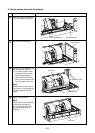
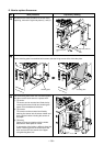
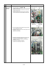
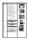
1. Detachment
1) Carry out work of 1 of
1
.
2) Remove connectors connected to CDB board.
(Power supply, serial, upper/lower fan motor, 4-way
valve coil, PMV coil, compressor case thermo,
temperature sensor, IPDU crossover wire, DC15V,
DC280V)
3) Remove CDB board. (Supporters at 4 positions)
4) Attach a new CDB board.
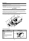
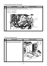
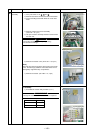
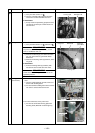
1. Detachment
1) Carry out works of 1 of
1
,
3
and
4
.
2) Remove the lead wire connected to the noise filter
board. (Power supply crossover wire, fuse
crossover wire, terminal block crossover wire)
3) Remove the earth screw. (BT2T Ø4 × 6, 1 pc.)
4) Remove the noise filter board.
(Supporter: 4 positions)
5) Attach a new noise filter board.
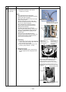
Upside of fan motor
4-way valve coil
connector
Serial crossover wire
connector
Upper fan
motor connector
Power supply
connector
PMV coil
PMV coil
connector
connector
IPDU crossover wire
IPDU crossover wire
connector
connector
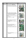
PMV coil
connector
IPDU crossover wire
connector
Compressor
case thermo
connector
Lower
fan motor connector
Temperature sensor connector
Fuse crossover
wire terminal
Power supply
crossover wire terminal
Terminal block crossover wire terminal
Earth
screw
DC15V
DC15V
DC280V
DC280V
DC15V
DC280V
CDB board
CDB board
CDB board
Electric parts box
(B)
Screw Bundling band
Power supply
Power supply
Screw
Screw
Supporter
Supporter
Power supply
Screw
Supporter
Replacement
of electric parts
CDB board
Replacement
of electric parts
Noise filter
board
5
6