


– 68 –
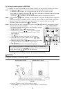
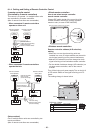
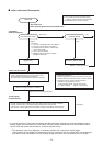
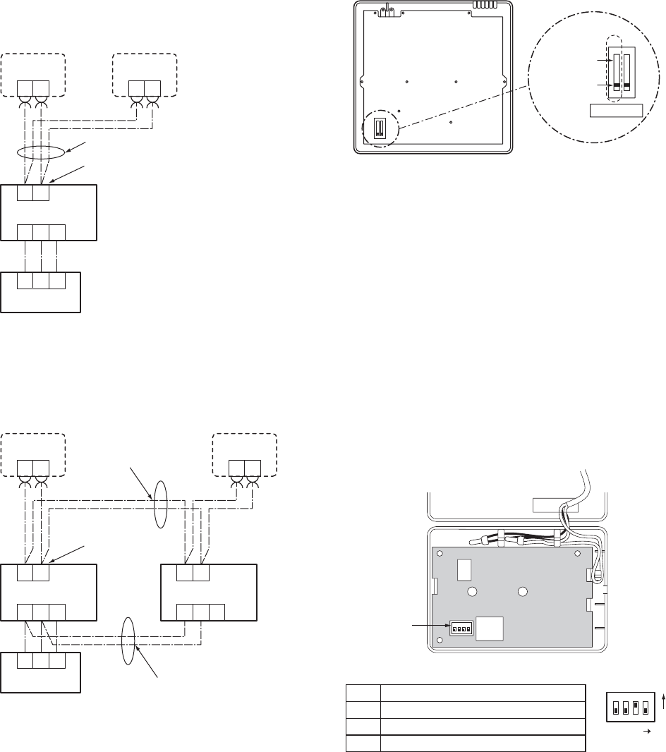
8-1-4. Cabling and Setting of Remote Controller Control
(Setup method)
One or multiple indoor units are controlled by two
remote controllers.
(Max. 2 remote controllers are connectable.)
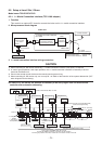
2-remote controller control
(Controlled by 2 remote controllers)
This control is to operate 1 or multiple indoor units
are controlled by 2 remote controllers.
(Max. 2 remote controllers are connectable.)
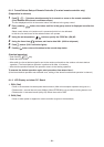
• When connected 2 remote controllers
operate an idoor unit
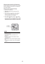
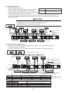
<Wired remote controller>
How to set wired remote controller
as sub remote controller
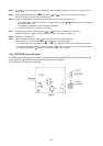
Change DIP switch inside of the rear side of the
remote controller switch from remote controller
master to sub. (In case of RBC-AMT32E)
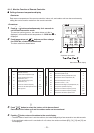
• When connected 2 remote controllers
operate the twin
Terminal block for
remote controller cables
Remote controller
cables (Procured locally)
Indoor unit
Outdoor unit
Remote controller
switch (Sub)
Remote controller
switch (Master)
Sold
separately
21 3
21
3
BA
BABA
Sold
separately
Terminal block for
remote controller cables
Indoor unit 1
Outdoor unit
Remote controller
switch (Sub)
Remote controller
switch (Master)
Sold
separately
21 3
21
3
BA
BABA
Indoor unit 2
21 3
B
A
Sold
separately
Remote controller
inter-unit wire
(Procured locally)
Inter-unit wiring
between indoor units
(Procured locally)
1 2
1 2
12
Remote controller (Inside of the rear side)
Sub remote
controller
Master remote
controller
DIP switch
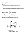
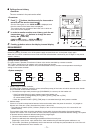
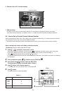
<Wireless remote controller>
Remote controller address (A-B selection)
setting
• When two or more signal receiving units are
installed in a room, a unique address can be set for
each signal receiving unit to prevent interference.
• Address (A-B selection) must be changed on both
signal receiving unit and wireless remote controller.
• For the details of address change (A-B selection) on
wireless remote controller, refer to the owner’s
manual.
Turn off the indoor unit power supply. Turn on the bit 3
of DIP switch SW30 on the signal receiving unit P.C.
board.
The setting change is shown below.
DIP-Switch [SW30]
4 ON=Follower OFF=Header
3 ON=B OFF=A
2 Not used
1 Not used
SW30
SW30
Bit3 : OFF ON
ON
1
ON
234