


– 58 –
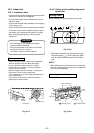
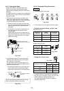
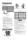
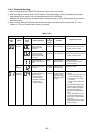
Packed Valve handling precautions
• Open the valve stem all the way; but do not try to
open it beyond the stopper.
• Securely tighten the valve stem cap with torque in
the following table:
Hexagonal wrench is required.
Fig. 10-4-10
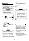
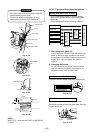
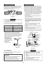
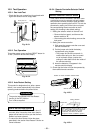
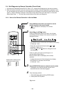
10-4-5. Wiring Connection
1. Remove the valve cover, the electric parts cover
and the cord clamp from the outdoor unit.
2. Connect the connecting cable to the terminal as
identified by the matching numbers on the
terminal block of indoor and outdoor unit.
3. Insert the power cord and the connecting cable
fully into the terminal block and secure it tightly
with screws.
4. Insulate the unused cords (conductors) from
water entering in the outdoor unit. Locate them
so that they do not touch any electrical or metal
parts.
5. Secure the power cord and the connecting cable
with the cord clamp.
6. Attach the electric parts cover and the valve
cover on the outdoor unit.
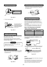
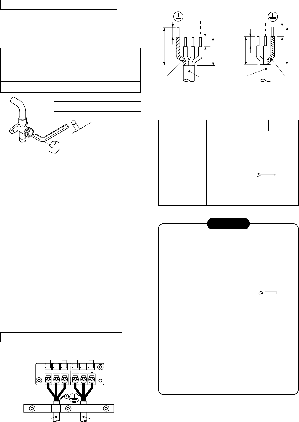
Stripping length of connecting cable
Fig. 10-4-11
Fig. 10-4-12
4mm
123 LN
Terminal block
Connecting cable Power cord
30
30
10
L
N
1012
3
10
10
40
40
Earth line Earth line
Connecting
cable
Power cord
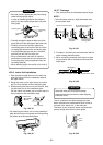
Gas side (Ø12.7 mm)
Gas side (Ø9.52 mm)
Liquid side (Ø6.35 mm)
Service port
50 to 62 N•m (5.0 to 6.2 kgf•m)
33 to 42 N•m (3.3 to 4.2 kgf•m)
14 to 18 N•m (1.4 to 1.8 kgf•m)
14 to 18 N•m (1.4 to 1.8 kgf•m)
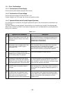
CAUTION
• Incorrect wiring connection may cause electri-
cal parts to burn out.
• Be sure to comply with local regulations/codes
when running the wire from outdoor unit to
indoor unit.
(Size of wire and wiring method etc.)
• Every wire must be securely connected.
• This installation fuse (25A D type )
must be used for the power supply line.
• If incorrect or incomplete wiring is carried out,
fire or smoke may result.
• Prepare the power supply for the exclusive use
of the air conditioner.
• This product can be connected to the main
breaker.
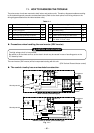
Connection to fixed wiring:
A switch which disconnects all poles and has a
contact separation of at least 3 mm must be
incorporated in the fixed wiring when connect-
ing to a main breaker circuit.
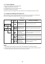
Model RAS-
Power source
Maximum running
current
Installation fuse
rating
Power cord
Connection cable
10GAVP-E 13GAVP-E 16GAVP-E
220 – 240 V ~50 Hz
220 V ~60 Hz
12 A
25A (D type )
H07RN-F or 245IEC66 (1.5 mm²)
H07RN-F or 245IEC66 (1.0 mm²)