


– 56 –
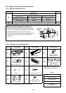
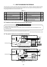
Base plate
9 Drain nipple
10
Water-proof rubber caps
(supplied with the outdoor unit)
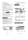
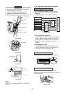
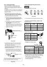
10-4-2. Draining the Water
• Holes are provided on the base plate of the
outdoor unit to ensure that the defrost water
produced during heating operations is drained off
efficiently.
If a centralized drain is required when installing the
unit on a balcony or wall, follow the steps below to
drain off the water.
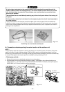
1. Proceed with water-proofing by installing the
water-proof rubber caps
in the 2 elongated
holes on the base plate of the outdoor unit. [How
to install the water-proof rubber caps]
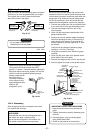
1) Place four fingers into each cap, and insert
the caps into the water drain holes by pushing
them into place from the underside of the
base plate.
2) Press down on the outer circumferences of
the caps to ensure that they have been
inserted tightly.
(Water leaks may result if the caps have not
been inserted properly, if their outer circumfer-
ences lift up or the caps catch on or wedge
against something.)
Fig. 10-4-2
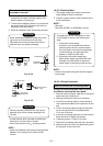
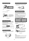
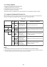
2. Install the drain nipple
and a commercially
available drain hose (with 16 mm inside diam-
eter), and drain off the water.
(For the position where the drain nipple
is
installed, refer to the installation diagram of the
indoor and outdoor units.)
• Check that the outdoor unit is horizontal, and
route the drain hose at a downward sloped
angle while ensuring that it is connected tautly.
Do not use ordinary garden hose, but one can
flatten and prevent water from draining.
Fig. 10-4-3
Commercially available
drain hose
Base plate
9 Drain nipple
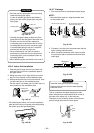
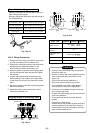
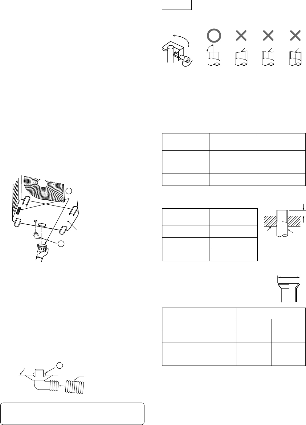
10-4-3. Refrigerant Piping Connection
Flaring
1. Cut the pipe with a pipe cutter.
Fig. 10-4-4
2. Insert a flare nut into the pipe, and flare the pipe.
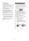
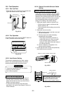
• Projection margin in flaring : A (Unit : mm)
Rigid (Clutch type)
Fig. 10-4-5
Imperial (Wing nut type)
• Flaring size : B (Unit : mm)
Fig. 10-4-6
• In case of flaring for R410A with the conventional
flare tool, pull it out approx. 0.5 mm more than that
of R22 to adjust to the specified flare size.
The copper pipe gauge is useful for adjusting
projection margin size.
90˚
Obliquity Roughness Warp
Die Pipe
A
+0
–0.4
B
Outer dia. of
copper pipe
6.35
9.52
12.7
R410A
tool used
0 to 0.5
0 to 0.5
0 to 0.5
Conventional
tool used
1.0 to 1.5
1.0 to 1.5
1.0 to 1.5
Outer dia. of
copper pipe
6.35
9.52
12.7
R410A
1.5 to 2.0
1.5 to 2.0
2.0 to 2.5
Outer dia. of copper pipe
6.35
9.52
12.7
B
R410A R22
9.1 9.0
13.2 13.0
16.6 16.2