– 50 –
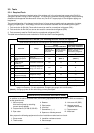
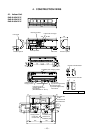
10-3. Indoor Unit
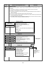
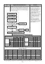
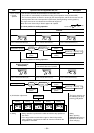
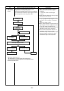
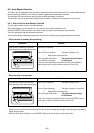
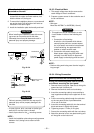
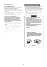
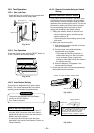
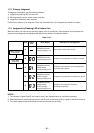
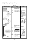
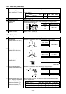
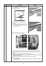
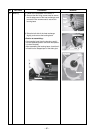
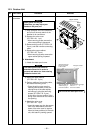
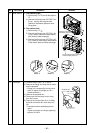
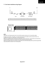
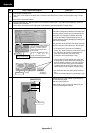
10-3-1. Installation Place
• A place which provides enough spaces around the
indoor unit as shown in the diagram.
• A place where there are no obstacle near the air
inlet and outlet.
• A place which allows easy installation of the piping
to the outdoor unit.
• A place which allows the front panel to be opened.
• The indoor unit shall be installed so that the top of
the indoor unit is positioned at least 2m in height.
• Also, avoid putting anything on the top of the
indoor unit.
CAUTION
• Direct sunlight on the indoor unit wireless
receiver should be avoided.
• The microprocessor in the indoor unit should
not be too close to r-f sources.
(For details, see the owner's manual.)
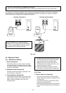
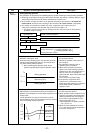
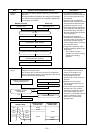
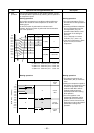
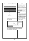
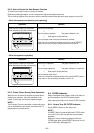
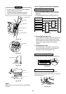
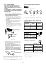
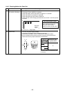
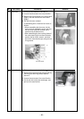
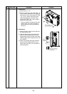
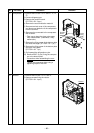
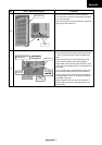
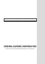
Remote controller
• Should be placed where there are no obstacles,
such as curtains, that may block the signal.
• Do not install the remote controller in a place
exposed to direct sunlight or close to a heating
source, such as a stove.
• Keep the remote controller at least 1 m away from
the nearest TV set or stereo equipment.
(This is necessary to prevent image disturbances or
noise interference.)
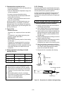
• The location of the remote controller should be
determined as shown below.
Fig. 10-3-1
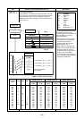
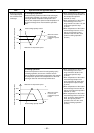
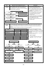
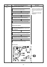
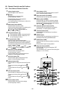
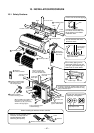
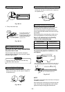
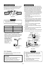
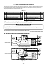
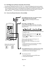
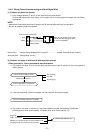
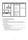
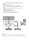
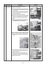
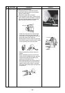
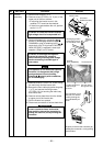
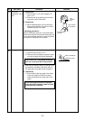
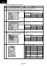
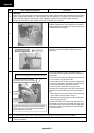
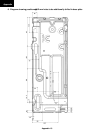
10-3-2. Drilling a Hole and Mounting Instal-
lation Plate
Drilling a hole
When install the refrigerant pipes from the rear.
Fig. 10-3-2
1. After determining the pipe hole position on the
installation plate (
ð
) drill the pipe hole (Ø65
mm) at a slight downward slant to the outdoor
side.
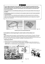
NOTE :
• When drilling into a wall that contains a metal lath,
wire lath or metal plate, be sure to use a pipe hole
brim ring sold separately.
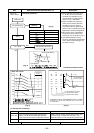
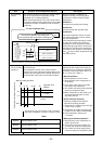
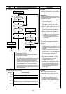
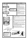
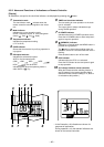
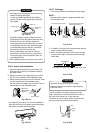
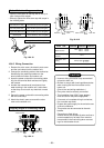
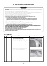
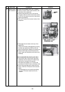
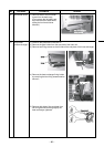
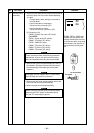
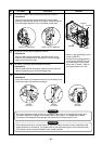
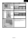
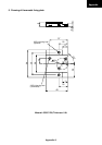
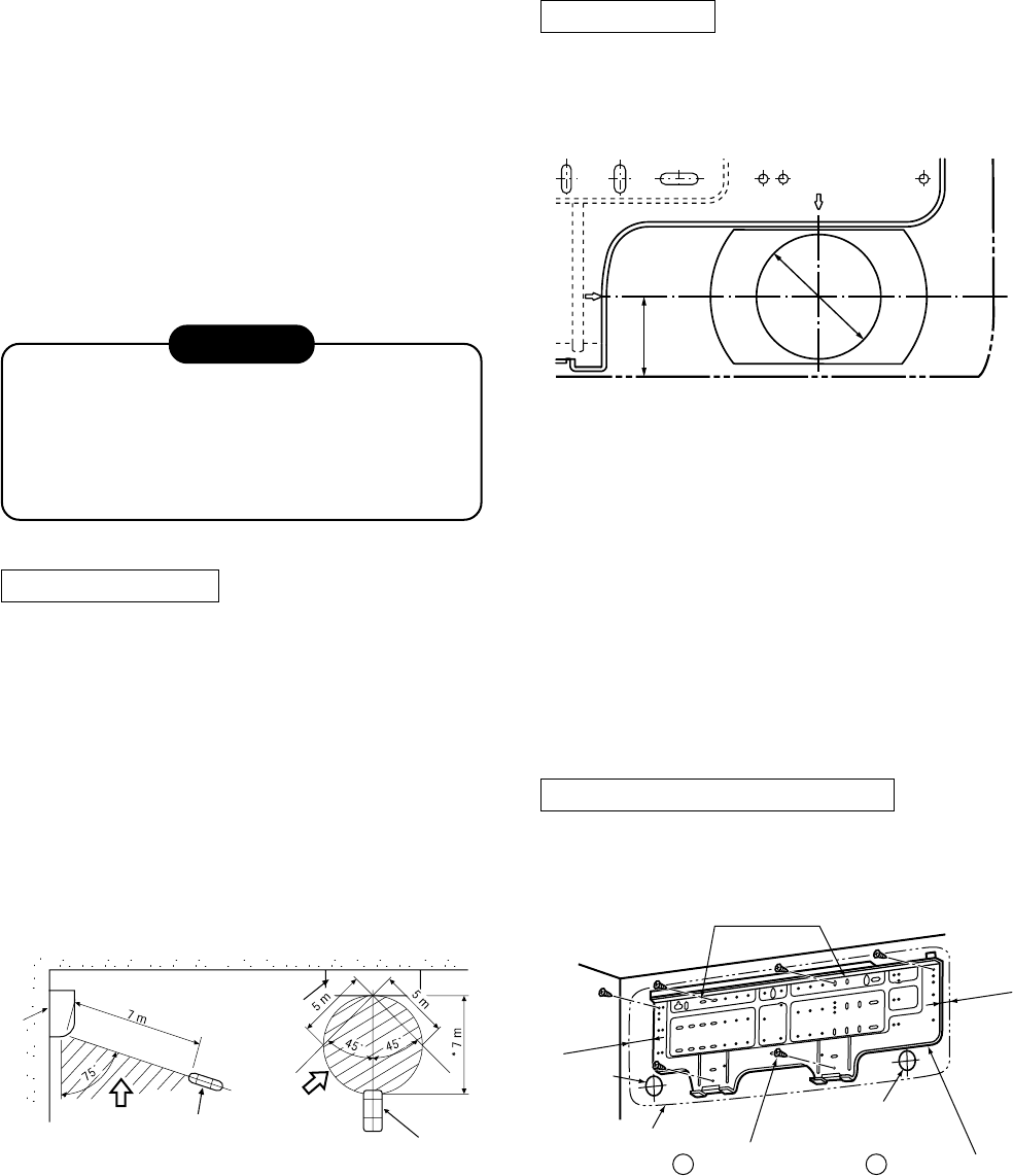
Mounting the installation plate
Indoor unit
(Top view)
(Side view)
Remote
controller
Remote controller
Indoor unit
*: Axial distance
Reception
range
Reception
range
42 mm
65 mm
The center of the
pipe hole
Pipe
hole
Fig. 10-3-3
91 mm
25 mm
Anchor bolt holes
Pipe hole
Pipe hole
Indoor unit
7 Mounting screw
1 Installation plate