


Lithium Battery Replacement
A 3.9V Lithium battery (P/N 363-2200) is installed in the timing mechanism to sustain the controller’s clock time and date for
approximately 10-years with no additional power applied.
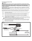
Step 1 – Place the controller’s power switch to OFF.
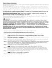
Step 2 – Remove the ribbon cable from the rear of the timing mechanism.
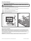
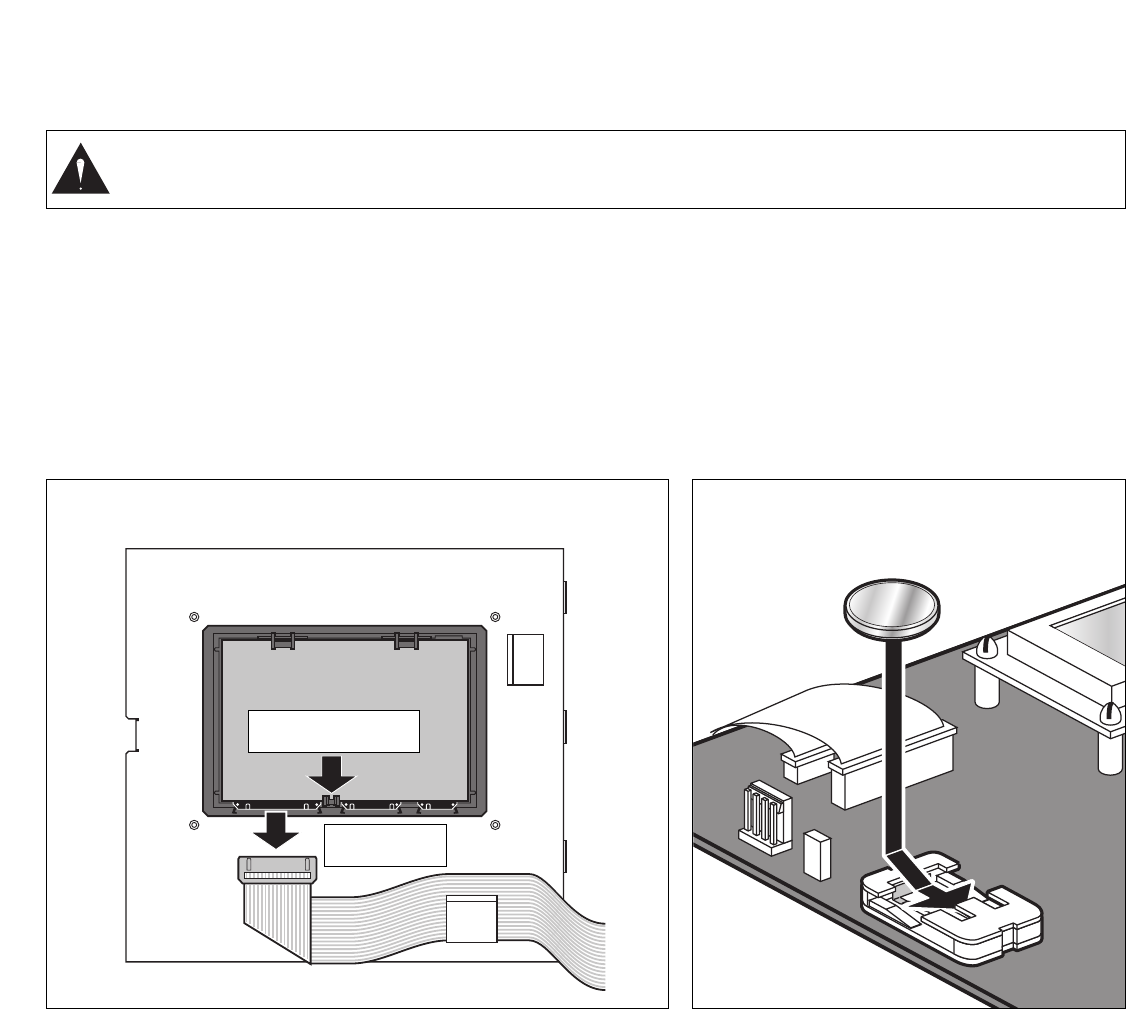
Step 3 – Remove timing mechanism’s circuit board by pushing the retaining clip downward while carefully pulling the PCB
board. See Figure 6.
Step 4 – Secure the Lithium battery into the battery socket. See Figure 7.
Step 5 – Reattach the circuit board to the timing mechanism.
Step 6 – Secure the ribbon cable back to the timing mechanism socket.
Step 8 – Place the controller’s switch to ON.
Electromagnetic Compatibility
Domestic: This equipment has been tested and found to comply with the limits for a FCC Class A digital device, pursuant to
part 15 of the FCC Rules. These limits are designed to provide reasonable protection against harmful interference when the
equipment is operated in a commercial environment. The equipment generates, uses, and can radiate radio frequency energy
and, if not installed and used in accordance with the instruction manual, may cause harmful interference to the radio
communications. Operation in a residential area is likely to cause harmful interference in which case the user will be required to
correct the interference at his own expense.
International: This is a CISPR 22 Class A product. In a domestic environment, this product may cause radio interference, in
which case the user may be required to take adequate measures.Each stations can activate up to two solenoids.
© 2008 The Toro Company, Irrigation Division • An ISO-9000-Certified Facility Form Number 373-0399 Rev. C
WARNING! DANGER OF EXPLOSION IF BATTERY IS INSTALLED INCORRECTLY. REPLACE ONLY WITH THE
SAME OR EQUIVALENT TYPE OF BATTERY. ALWAYS DISPOSE OF USED BATTERIES ACCORDING TO THE
MANUFACTURER’S INSTRUCTIONS.
Push Retaining Clip
to Release the PCB
Disconnect the
Ribbon Cable
Figure 6 Figure 7