


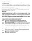
Grounding Communication Cable
IMPORTANT!
Cable Splices: In order for the wire connections to comply with the 2005 edition of the National Electric Code®
Article 300.5 (Underground Installations) and 110.14 (Electrical Connections), in wet or damp locations, the connector
must be listed under specification “UL 486D” if installed in a valve box. It must be listed under specification “UL 486D-
Direct Burial” if buried in dirt. This requirement applies to all electrical connections in wet or damp locations,
regardless of voltage. The 3M DBY-6 and DBR-6 are listed as “UL 486D-Direct Burial” and meet these requirements for
all underground installations.
Cable Burial Depth: The TDC decoder operate at voltages between 30–40 volts. The 2005 edition of the National
Electrical Code®, Article 300-5, requires that wires and cables subjected to voltages higher than 30 volts are to have a
minimum cover of 24" (60.96 cm).
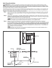
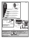
The optional lightning arrester (Toro P/N DEC-SG-LINE) is available to protect the decoder module in lightning prone areas.
Without lightning arrester, the decoder are vulnerable to lightning damage. In order for these arrester to discharge lightning
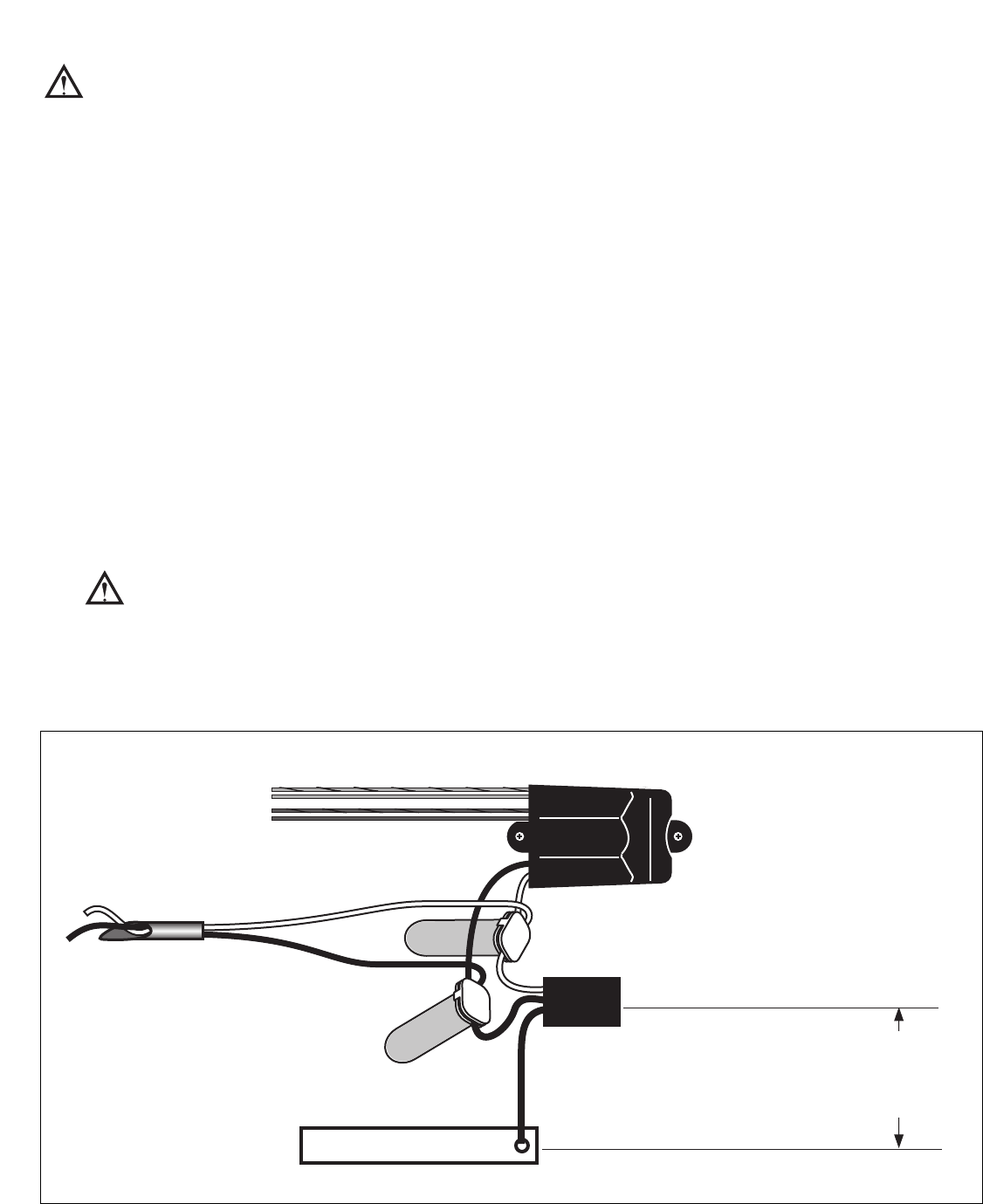
energy efficiently, they must be properly grounded. Figure 5 illustrates the proper grounding and wiring of the arrester.
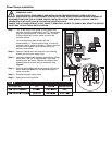
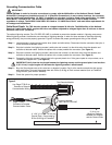
Step 1 – Locate decoder’s power/communication wires (black and white wires). Disconnect the wire connectors that joins it
to the controller-to-decoder cable.
Step 2 – Strip the insulation from lightning arrester’s white wire and connect it to the white wires from the decoder and
controller-to-decoder cable. Secure the splices with a water proofed wire connector. (See Figure 5.)
Step 3 – Strip the insulation from lightning arrester’s black wire and connect it to the black wires from the decoder and
controller-to-decoder cable. Secure the splices with a water proofed wire connector. (See Figure 5.)
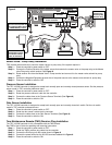
Step 4 – Connect the lightning arrester’s ground wire to the ground plate’s wire. If the ground plate is not pre-wired, use a
10 AWG bare copper wire. (See Figure 5.)
IMPORTANT! Verify that the wire length between the lightning arrester and the ground plate is no less than
3' (91.44 cm). Longer lengths will decrease the lightning arrester’s effectiveness.
Step 5 – Bury the Ground plate next to the valve box or decoder’s location. Set it at the maximum depth that the ground
wire would allow. Surround the ground plate with 50 lbs (2.68 Kg) of Earth contact material such as PowerSet
®
(Paige Electric, part number 1820058).
Step 6 – Check the system for proper operation.
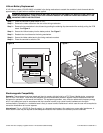
Figure 5
3' (91.4 cm)
Minimum Distance
Between the Arrester
and the Ground Plate
Lightning Arrester
Toro P/N DEC-SG-LINE
4'' x 36'' (10.16 cm x 91.44 cm)
Ground Plate - Surrounded by
50 lbs (2.68 Kg) of PowerSet
®
Toro Decoder Module
Paige P7350D
Controller-to-Decoder
Communication Cable
Use Paige P7351D for
Decoder-to-Solenoid
Communication Wiring