Power Source Installation
Step 1 – Turn off the power at the power source location and
place the controller’s power switch to OFF. Connect and
route the appropriate size 3-conductor cable (10 AWG
[2.5mm
2
] maximum) from the power source to the
controller cabinet.
The provided power cable access hole can
accommodate a 1" (25mm) conduit fitting. If conduit is
required, install a section of flexible 1" (25mm) electrical
conduit from the power source conduit box to the
cabinet’s access hole.
Step 2 – Open the cabinet door and remove the two retaining
screws from the power supply cover.
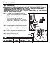
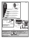
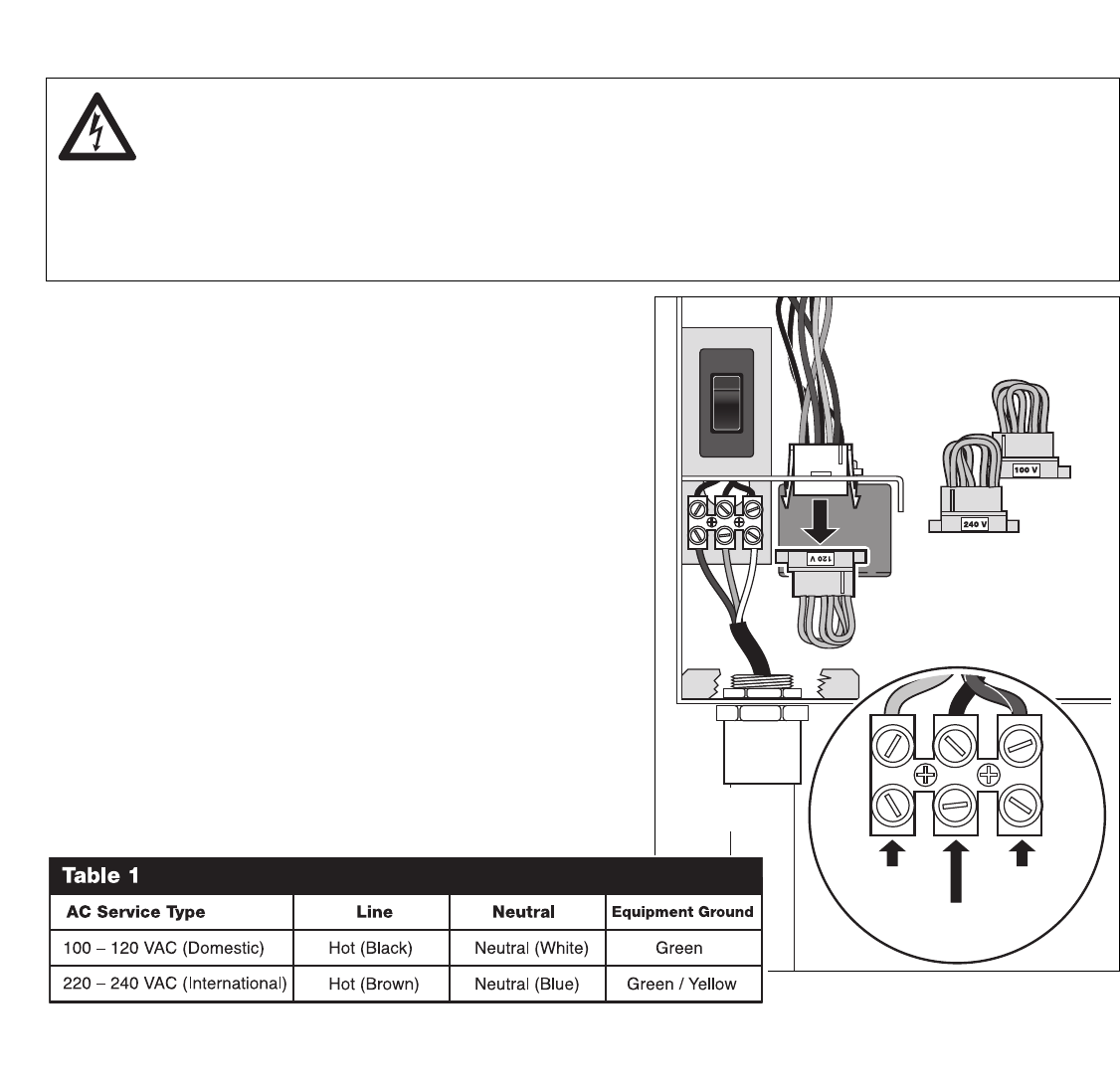
Step 3 – Locate the voltage cable assembly and note the voltage
on the label. The TDC is equipped with 120V cable
assembly from the factory. Replace the voltage cable
assembly with the proper rating as necessary. See
Figure 3.
Step 4 – Strip the power cables and secure them to the terminal
block. Reference Table 1 for the appropriate type of
power connection.
Step 5 – Reinstall the power supply cover.
Step 6 – Apply power to the controller.
WARNING! AC POWER WIRING MUST BE INSTALLED AND CONNECTED BY QUALIFIED
PERSONNEL ONLY.
ALL ELECTRICAL COMPONENTS AND INSTALLATION PROCEDURES MUST COMPLY WITH ALL
APPLICABLE LOCAL AND NATIONAL ELECTRICAL CODES. SOME CODES MAY REQUIRE A MEANS OF
DISCONNECTION FROM THE AC POWER SOURCE, INSTALLED IN THE FIXED WIRING, HAVING A CONTACT
SEPARATION OF AT LEAST 3mm IN THE LINE AND NEUTRAL POLES.
ENSURE THE AC POWER SOURCE IS OFF PRIOR TO SERVICING. FAILURE TO COMPLY MAY RESULT IN SERIOUS
INJURY DUE TO ELECTRICAL SHOCK HAZARD.
Figure 3
Line
Neutral
Voltage Cable
Assembly
Flexible Conduit
(Optional)
Equipment
Ground


