


NOTE: DIAGRAMS & ILLUSTRATION NOT TO SCALE.
8
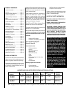
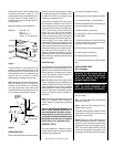
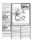
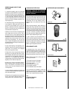
All appliances have a 3" long 3/8" NPT nipple
installed at the valve. To quickly and easily
complete the gas line routing, use the gas flex
line kit, Model GFLV.
Figure 9
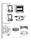
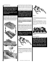
Step 3. Remove the nailing flanges from the
lower control compartment and install in place
with three (3) screws each. Align with the three
holes on each side of the appliance (refer to
Figure 5
).
Install the hood on all units. Position the hood in
the open area above the appliance door. Insert the
tabs, on each end of the hood, into the bracket at
each end. Bend the two tabs over to secure.
Step 4. Position appliance into prepared fram-
ing, secure with 6d nails at the nailing flange
along each side.
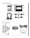
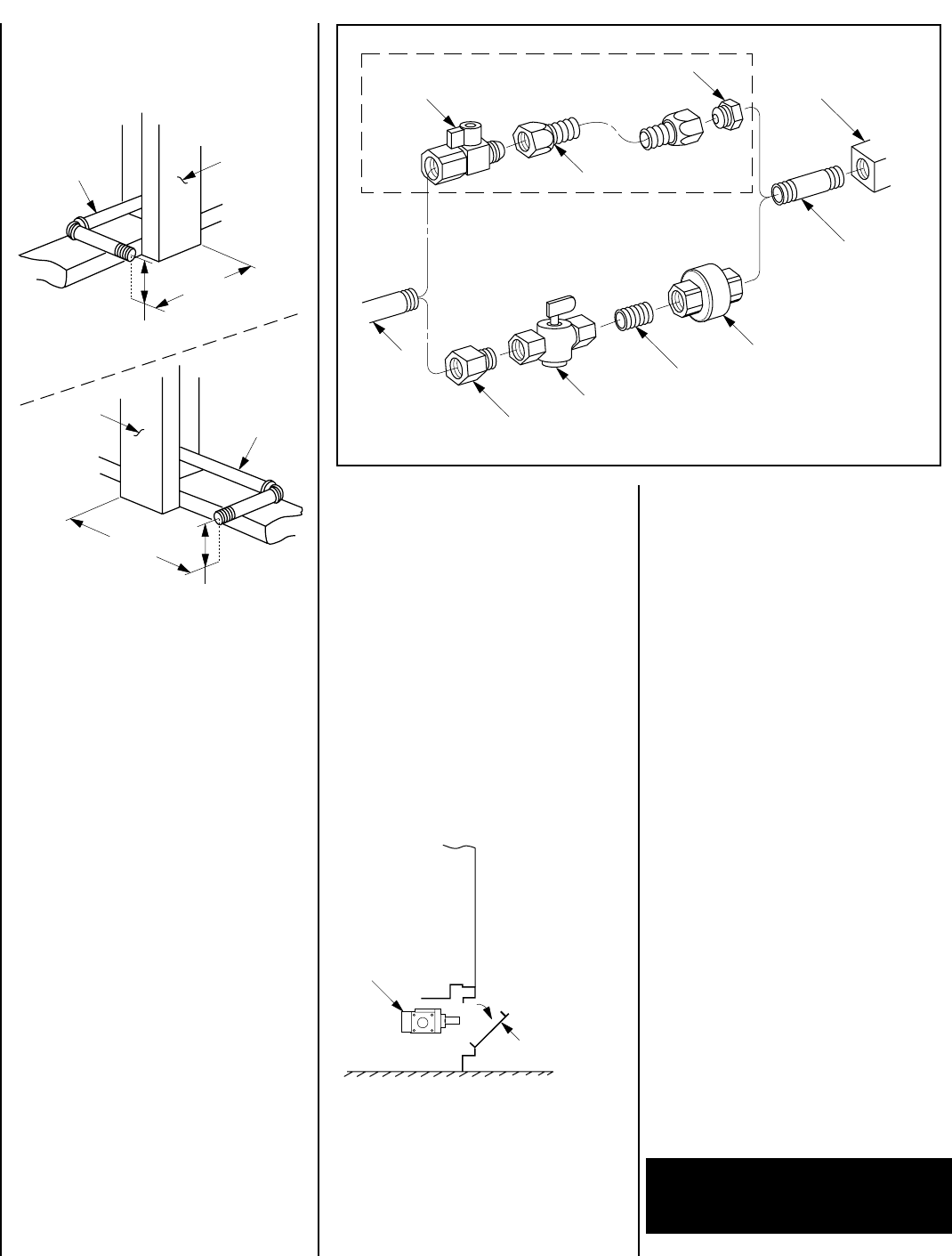
Step 5. Connecting Gas Line – Make gas line
connections. All codes require a shut-off valve
mounted in the supply line.
Figure 10
illus-
trates two methods for connecting the gas
supply. Installation methods and materials
must be in compliance with local codes.
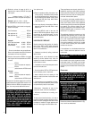
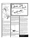
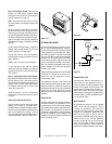
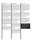
The gas control valve is located in the lower
control compartment. To access the valve
open the lower control compartment door
(
Figure 11
). The control valve has a 3/8" NPT
thread inlet port and is fitted with a 3" (76 mm)
long nipple, 3/8" NPT on both ends. Plan the
connections accordingly.
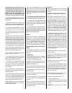
Route the gas line using techniques and mate-
rials prescribed by local and/or national codes.
If the gas line must be routed from the left hand
side (viewed from the gas controls), route the
gas line around the valve and connect to the
valve from the right hand side. The left hand
gas line opening has been offset to allow for
easy attachment of hard piping from the left
hand side, when hard piping (black iron) is
required by local codes.
For ease in installation, the offset is designed to
utilize (1) a 3/8" street elbow at the valve,
replacing the nipple provided with the appli-
ance and oriented to the rear, (2) a 6", 3/8"
nipple and (3) a 3/8" standard elbow returning
to the left and aligning with a gas line routed
through the left hand opening.
Figure 11
Figure 10
Control
Valve
Lower Control
Compartment Door
3-7/8"
(98 mm)
4"
(102 mm)
1/2" Gas
Line
Stud
Plate
Standard
Left Side
11-3/8"
(289 mm)
4-1/8"
(105 mm)
1/2" Gas
Line
Stud
Plate
Primary
Right Side (ST)
Gas Stub
1/2" x 3/8" Flare
Shut-Off Valve
3/8" Flex Tubing
3/8" NPT x 3/8"
Flare Fitting
3/8" Nipple, Standard
with all Units
3/8" Union
3/8" Close Nipple
3/8" Shut-Off Valve
1/2" x 3/8" Reducer
Gas Valve
Gas Flex Line Kit, Model GFLV
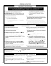
Turn on gas supply and test for gas leaks,
using a gas leak test solution (also referred to
as bubble leak solution).
Note: Using a soapy water solution (50% dish
soap, 50% water) is an effective leak test
solution but it is not recommended, because
the soap residue that is left on the pipes/
fittings can result in corrosion over time. Never
use an open flame to check for leaks.
A. Light the appliance (refer to safety and
lighting instructions on page 15) (
See *Note
).
B. Brush all joints and connections with the
gas leak test solution to check for leaks. If
bubbles are formed, or gas odor is detected,
turn the gas control knob to the “OFF” posi-
tion. Either tighten or refasten the leaking
connection and retest as described above.
C. When the gas lines are tested and leak free,
be sure to rinse off the leak testing solution.
D. When the gas lines are tested and leak free,
observe the individual tongues of flame on the
burner. Make sure all ports are open and
producing flame evenly across the burner. If
any ports are blocked, or partially blocked,
clean out the ports.
Secure all joints tightly using appropriate
tools and sealing compounds (ensure pro-
pane resistant compounds are used in
propane applications).
An external regulator must be used on all pro-
pane (L.P.G.) heaters, in addition to the regula-
tor fitted to the heater, to reduce the supply tank
pressure to 13" w.c. (maximum).
WARNING: CONNECTING DIRECTLY TO
AN UNREGULATED PROPANE TANK CAN
CAUSE AN EXPLOSION.