


NOTE: DIAGRAMS & ILLUSTRATION NOT TO SCALE.
5
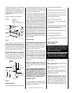
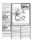
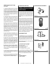
Carefully inspect the heater case and contents
for shipping damage and immediately inform
the dealer from whom you purchased the gas
fireplace if any damage is found.
The appliance is shipped with all gas controls
and components installed and pre-wired. Re-
move the shipping carton, exposing the screen
panel assemblies or optional (if installed) glass
doors. Remove wood slats and remove and
discard the wood slat mounting brackets.
Loosen and remove the three (3) 1/4"-20 x 1"
Phillips pan head screws at the three (3) tabs
located along the top of the screen or glass door
frame top edge. Tilt the frame outward and
disengage the three (3) tabs along the bottom
from the three (3) brackets at the bottom of the
firebox opening. Remove the door and set the
panel aside protecting it from inadvertent dam-
age. Retain the three (3) screws for use on
reassembly. Repeat the procedure (if required)
to gain access to the other side of the appliance.
Remove the logs, packaged inside the firebox
and also set aside.
Check Gas Type
This appliance can only be connected to the gas
type specified on the appliance data plate. This
appliance can not be modified in the field for a
different gas type. If the gas type to be used is
not the one specified contact the dealer to
obtain the correct gas appliance.
Note: Illustrations shown in this manual reflect
“typical” installations with nominal dimensions
and are for design and framing reference only.
Actual installations may vary due to individual
design preferences. However, always maintain
minimum clearances to combustible materials
and do not violate any specific installation re-
quirements.
Note: The following steps represent the normal
sequence of installation. Each installation is
unique, however, and might require a different
sequence.
CAUTION: HEATERS CREATE WARM AIR CUR-
RENTS. THESE CURRENTS MOVE HEAT TO
WALL SURFACES NEXT TO HEATER. INSTALL-
ING HEATER NEXT TO VINYL OR CLOTH WALL
COVERINGS OR OPERATING HEATER WHERE
IMPURITIES IN THE AIR (SUCH AS TOBACCO
SMOKE) EXISTS, MAY DISCOLOR WALLS.
ASSEMBLY STEPS
The typical sequence of installation follows,
however, each installation is unique resulting in
variations to those described.
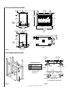
37-1/2"
(953 mm)
Min. to
Ceiling from
Top of
Appliance
Door
(See Figure 2)
0" Clearance
to Combustible
Side Wall
Combustible
Mantel
Max. Projection (See Figure 2)
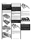
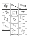
1. Construct the appliance framing.
2. Route gas supply line to appliance location.
3. Install nailing flanges. Install the hoods.
4. Position the appliance within the framing and
secure with nailing brackets.
5. Make connection to gas supply.
6. Assemble the Carbon Monoxide Safety
Shutoff (COSS).
7. Install the operating control switch and bring
in electrical service line for forced air circulat-
ing blower (optional equipment).
8. Mount forced air kit (optional equipment).
9. Install the logs and Rockwool.
10. Checkout appliance operation.
11. Install screen assembly or (optional) glass
door.
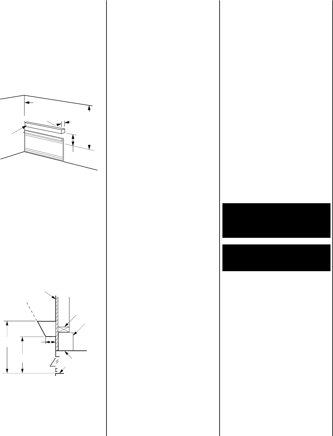
Figure 2
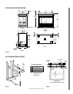
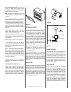
PREINSTALLATION
Check that all listed parts have been received.
Combustible
Finished Wall
Materials
Top of Appliance
VF Series
2"
(50 mm)
14"
(356 mm)
Top of Door Frame
Spacer
8''
(203 mm)
21"
(533 mm)
Header
Figure 1
A hearth extension is not required with this
appliance. If a hearth extension is used, do not
block the lower control compartment door. Any
hearth extensions used is for appearance only
and does not have to conform to standard
hearth extension installation requirements.
Note: Combustible wall finish materials and/or
surround materials must not be allowed to
encroach the area defined by the appliance
front face (black sheet metal). Never allow
combustible materials to be positioned in front
of or overlapping the appliance front face.
Combustible mantles may be installed above
the appliance (as shown in
Figure 2
). The
mantle projection may be extended beyond 8" if
the height above the firebox opening is in-
creased proportionately as detailed by the in-
crements shown.
Minimum clearance to combustibles are:
Appliance: each side - 1/2”
floor - 0"
adjacent wall - 0"
ceiling - 37-1/2” (953 mm)
INSTALLATION STEPS
Built-In Systems
WARNING: DO NOT ALLOW FANS TO
BLOW DIRECTLY INTO THE FIREPLACE.
AVOID ANY DRAFTS THAT ALTER
BURNER FLAME PATTERNS.
WARNING: DO NOT USE A BLOWER IN-
SERT, OR OTHER ACCESSORY NOT
APPROVED FOR USE WITH THIS HEATER.
Do not burn solid fuels in this listed unvented
gas room heater.
Note: Appliance Dimensional Specifications
are shown in Figure 3.
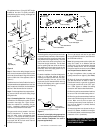
Step 1. Frame the VFST appliance as illus-
trated in
Figures 4 and 5
.
The header may be in direct contact with the top
metal spacers, but must not rest on them or be
notched to fit around them.
Step 2. Route a 1/2" (13 mm) gas line along the
left or right side framing (
Figure 6
). The primary
method for the SF is from the right end (when
viewed from the control side) straight in to the
valve. ST's may be routed as the PF's are, from
the left using an assembly composed of a 3/8"
street elbow, a 3/8" elbow and 3/8" 6" long nipple.