


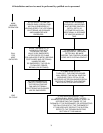

All installations and services must be performed by qualified service personnel.
31
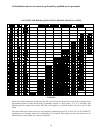
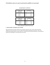
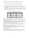
FORMULA:
(tons of cooling) x (400 CFM per ton) (144 square inches per foot) = filter area sq.inches
(max. air velocity of filter from table 3 for the filter type) = length x width of
filter in inches
EXAMPLE: If you had a CHB1-100 furnace and 4 tons of cooling and a standard permanent filter.
4 tons x 400 CFM x 144 = 460 square inches for cooling
500
For heating a CHB1-100 needs 394 square inches of filter. The filter system must be designed for the larger CFM
requirement determined for cooling of 460 square inches. A filter would have to be sized so that the area (length X
width) was at least 460 sq. in.
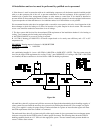
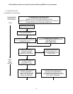
L. WIRING
All wiring shall be performed by a qualified electrician or service person. The wiring must comply with local codes,
the instructions in this manual, and in the absence of codes with the National Electrical Code (ANSI/NFPA-70 or
latest edition).
1. The following items are guidelines to complete the wiring portion of the installations.
a. A separate power supply circuit with over current protection and a disconnect switch must be provided. See
furnace specifications or furnace rating label for maximum fuse size.
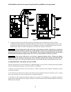
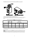
b. All CHB1 and CDB1 Series furnaces are supplied with a fuse disconnect switch box to be mounted on the
outside surface of the right or left side casing so a fuse disconnect can be mounted on the furnace. Make the 115
volt supply connection in this junction box. A green screw and a strain relief are provided in order to connect the
power supply ground wire and provide strain relief for the 115 volt power leads from the furnace in the fuse
disconnect box. A disconnect switch can be field mounted on the 2x4 box provided. If not, the disconnect switch
must be located reasonably close to and within sight of the furnace.
NOTICE: The hot surface igniter and operation of this furnace depends on correct polarity. The hot leg of the
supply circuit must be connected to the black line lead and the common leg to the white line lead in the field
mounted junction box. The hot leg must pass through the disconnect switch in all cases to prevent the hazard of
electrical shock when servicing.
IMPORTANT: The furnace must be grounded in accordance with local codes and with the National Electrical
Code (ANSI/NFPA NO. 70 or latest edition) when an external electrical source is utilized.
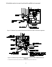
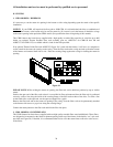
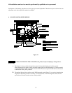
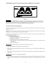
2. ELECTRONIC AIR CLEANER (EAC) AND HUMIDIFIER INSTALLATION
The ignition module on this furnace has designated terminals to control the operation of an electronic air cleaner
and/or humidifier. These terminals provide line voltage (110-20VAC) for the control of these accessories. (See
Figure 21). NOTICE: It is important to confirm that the operating voltage of the humidifier or EAC being installed
matches the output of this control. If not, a field supplied relay or transformer may be necessary to provide the
proper control and supply voltage for the accessory being installed. See the manufacturers instructions for the
humidifier or EAC for additional instructions.
3. THERMOSTAT ANTICIPATOR SETTING
Proper control of the indoor temperature can only be achieved if the thermostat is calibrated to the heating and/or
cooling cycle. A vital consideration of this calibration is related to the thermostat heat anticipator.
The proper thermostat heat anticipator setting is 0.8 AMPS for furnace operation only. To increase length of cycle,
increase setting of heat scale; to decrease length of cycle, decrease setting of heat scale.
Anticipators for the cooling operation are generally pre-set by the thermostat manufacturer and require no
adjustment.