


All installations and services must be performed by qualified service personnel.
22
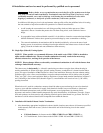
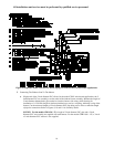
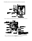
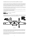
DO NOT! SILICONE OR SEAL
THIS CONNECTION IN
ANYWAY. MUST BE LOOSE
FIT WITH LEAKAGE BETWEEN
PVC AND METAL COLLAR.
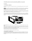
Figure 12: Typical Internal Air Intake Piping Arrangement for All Furnace Models
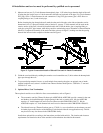
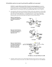
d. After trial fitting the entire combustion air intake system, use a PVC cement to glue all connections in
place, except the length of pipe between the combustion air fitting on the burner box and the first
fitting.
e. If the combustion air piping is installed in a warm, humid place, such as a laundry room or above a
suspended ceiling, it must be insulated with a 1-inch thick, foil-faced fiberglass insulation, or an
equivalent product, to help prevent the outside surface of the pipe from sweating.
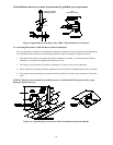
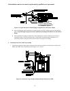
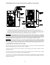
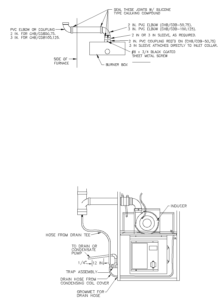
I. Condensate Drain Line And Trap Assembly
1. The following diagrams depict typical condensate drain and trap connections for the furnace models series
CHB1 and CDB1, refer to the illustrations in Figures 14, 15, and 16.
Figure 14. Condensate Trap Assembly Mounted On the Model Series CHB1