


All installations and services must be performed by qualified service personnel.
37
FORMULA: BTU/CU FT X NUMBER OF CU FT X 3600 SECONDS = INPUT BTU/HR
EAMPLE: 1025 BTU/CU FT X 2 CU FT X 3600 = 98,633 BTU INPUT 74.8 SECONDS
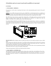
Check for the model number of this furnace, its input, the type of gas and the manifold pressure on the
information plate located on the vestibule panel behind the upper front panel. If using the above example, the
furnace was a CHB-100 model and the 98,663 BTUinput would be acceptable because it was within 2% of the
listed input of 100,000.
Make sure that the gas supply pressure to the furnace falls within the maximum range of 4 ½” to 14” wc pressure
on natural gas and 11.0” to 14.0” w.c. on Propane gas. The pressure to the furnace must be checked while the
furnace burner and any other gas appliances on the same supply system are operating, using the 1/8” in. plugged
tap shown in Section III, J, Fig. 18 of this manual.
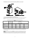
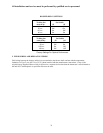
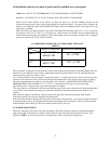
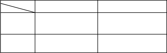
GAS PRESSURE CHART FOR ALL CHB1 MODEL FURNACES
TABLE 4
SUPPL Y PRESURE
M ANI FOL D PRESSURE
NAT
LP
MAX 14" WC
MIN 4.5" WC
MAX 14" WC
MIN 11" WC
3.5" .3" WC
10.0" + .3" WC
+
-
-
This gas furnace is equipped with a fixed orifice sized for the manifold pressure shown on the information plate. The
input can only be increased or decreased by adjusting the manifold pressure. Remove the 1/8" threaded pipe plug
located on the top right side of the gas valve.
Us a U tube manometer or pressure gage to measure the pressure. To adjust the pressure, remove the screw from the
regulator on the outlet side of the gas valve and using the adjustment allen screw, decrease the pressure by turning
the screw counterclockwise or increase it by turning the screw clockwise. ADJUSTMENTS TO THE LISTED
PRESSURE MUST NOT EXCEED 0.3” w.c. A 0.3” w.c. Adjustment will increase or decrease the input
approximately 4.0%. Replace screw (cap) when adjustment is complete.
The correct input can be assumed if the furnace manifold pressure is the same as that shown on the information label
if a gas meter is not available for natural gas or the unit is installed on liquefied petroleum gases which are not
metered.
Shut off the gas supply to the furnace. Remove the pressure gage and re-install the pipe plug using a thread
compound resistant to the action of Liquefied Petroleum gases.
If the rated input cannot be obtained with the present orifice at the correct pressure, your local gas supplier will assist
in sizing the proper orifice. Our Engineering Department will gladly assist in sizing the orifice if you provide them
with the heating value in BTU per cubic foot and the specific gravity of the gas.
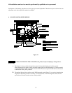
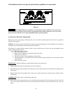
D. BURNER ADJUSTMENT
This unit is designed to not require any burner adjustment. The flames should be checked by looking through the
sight glass located on the burner box. Burner flames should be clear, blue and almost transparent in color. (See
Figure 23). NOTE: It is not unusual to have orangish flames visible in the tube for Propane gas.